


INTRODUCTION AND INSTALLATION PAGE 3
INTRODUCTION
This manual contains information that is the result of carefully conducted engineering and research efforts. It is
designed to supply adequate instructions for the safe and efficient installation, operation maintenance of your
pump. Failure or neglect to properly install, operate or maintain your pump may result in personal injury,
property damage or unnecessary damage to the pump.
Variations exist in both the equipment used with these pumps and the particular installation of the pump and
driver. Therefore, specific operating instructions are not within the scope of this manual. The manual contains
general rules for installation, operation and maintenance of the pump.
Observe all caution or danger tags attached to the pump or included in this manual.
INSTALLATION
1. GENERAL
CAUTION: CAREFULLY READ ALL SECTIONS OF THIS MANUAL AND ALL OTHER
INSTRUCTION MANUALS PROVIDED BY MANUFACTURERS OF OTHER
EQUIPMENT SUPPLIED WITH THIS PUMP.
Upon receipt of the shipment, unpack and inspect the pump and driver assemblies and individual parts to
ensure that none are missing or damaged. Carefully inspect all boxes and packing material for loose parts
before discarding them. Report immediately to the transportation company involved, and to the factory, any
missing parts or damage incurred during shipment, and file your “damaged and/or lost-in-shipment” claim with
the carrier.
Horizontal pump and driver assemblies mounted on a common base are accurately aligned at the factory.
However, alignment may be disturbed in transit or during installation. It must be checked after the unit is
leveled on its foundation, after the grouting has set and the foundation bolts are tightened, and after the piping
is completed.
When the pump and driver are mounted on separate base structures, the pump should be leveled and aligned
first, then the driver leveled and aligned with the pump. With separate bases, a flexible shaft between the pump
and driver must be used.
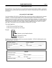
2. NET POSITIVE SUCTION HEAD (NPSH)
NPSH can be defined as the head (energy) that causes liquid to flow through the suction pipe and enter the eye
of the impeller.
NPSH is expressed in two values: (1) NPSH required (NPSH
R
) and (2) NPSH available (NPSH
A
). It is essential
that NPSH
A
be always greater than NPSH
R
to prevent cavitation, vibration, wear and unstable operation.
NPSH
R
is a function of the pump design and therefore varies with the model, size, capacity and speed of the
pump. The value for your pump can be obtained from your pump performance curve or from the factory.
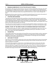
A. When the source of the liquid is above the pump:
NPSH
A
= barometric pressure (feet) + static suction head (feet) – friction losses in suction piping
(feet) – vapor pressure of liquid (feet)
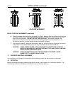
B. When the source of the liquid is below the pump:
NPSH
A
= barometric pressure (feet) - static suction lift (feet) – friction losses in suction piping (feet)
– vapor pressure of liquid (feet)