


INSTALLATION (continued) PAGE 5
7. GROUTING
When the alignment is correct, the unit should be grouted using high-grade non-shrinking grout. The entire
base should be filled with grout. Be sure to fill all gaps and voids. Allow the grout to fully cure before firmly
tightening the foundation bolts. Then recheck the alignment before connecting the piping.
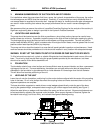
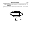
8. PIPING
CAUTION: ALL PIPING CONNECTIONS MUST BE MADE WITH THE PIPING IN A FREE
SUPPORTED STATE, AND WITHOUT THE NEED TO APPLY VERTICAL OR
SIDE PRESSURE TO OBTAIN ALIGNMENT OF THE PIPING WITH THE
PUMP FLANGE.
CAUTION: AFTER ALL THE PIPING IS CONNECTED, THE PUMP AND DRIVER
ALIGNMENT MUST BE RECHECKED.
All piping should be independently supported near the pump so that pipe strain will not be transmitted to the
pump casing. The suction and discharge piping should be one or two sizes larger than the pump flange sizes,
especially where the piping is of considerable length. Any flexible joints installed in the piping must be equipped
with tension rods to absorb piping axial thrust. Care must be exercised in arranging elbows so as not to
generate vortexing in the pump inlet.
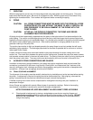
The suction pipe must be air tight and sloped upward to the pump flange to avoid air pockets that will impair
satisfactory pump operation. The discharge pipe should be as direct as possible with a minimum of valves to
reduce pipe friction losses.
A check valve and closing valve should be installed in the pump discharge line and a closing valve in the
suction line. The check valve, between the pump and the closing valve, protects the pump from water hammer
and prevents reverse rotation in the event of power failure. The closing valves are used in priming, starting and
when the pump is shut down. The pump must never be throttled by the use of a valve in the suction line.
9. AUXILIARY PIPING CONNECTIONS AND GAUGES
In addition to the primary piping connections, your pump may require mechanical seal and seal water filter
connections, connections to the lantern ring (see the “Packing Box” and “Mechanical Seal” sections of this
manual), stuffing box drain, discharge and suction flange gauges, casing relief valve drain or baseplate drain
connections. All these lines and gauges should now be installed.
10. FINAL COUPLING ALIGNMENT
The alignment of the coupling must be carefully checked during installation and as the last step before starting
the pump. If realignment is required, the piping should be disconnected first. After aligning, reconnect the
piping in accordance with the previous instructions and again recheck the alignment.
A flexible coupling must not be used to compensate for misalignment resulting from poor installation or
temperature changes.
Aurora Pumps are supplied with several different types of commercial couplings. Refer to the coupling
manufacturer’s installation instructions for maximum allowable misalignment.
NOTE: FOR MAXIMUM LIFE, KEEP MISALIGNMENT VALUES AS NEAR TO ZERO AS POSSIBLE.
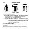
A. Check parallel misalignment by placing a straightedge across the two coupling flanges and
measuring the maximum offset at various points around the periphery of the coupling. DO NOT
ROTATE THE COUPLING. If the maximum offset exceeds manufacturer’s recommendations,
realign the coupling.