


PAGE 4 INSTALLATION (continued)
3. MINIMUM SUBMERGENCE OF SUCTION PIPE AND PIT DESIGN
For installations where the pump draws fluid from a sump, the hydraulic characteristics of the pump, the suction
inlet submergence and NPSH must be considered. Generally, it is required that an evenly distributed flow of
non-aerated water be supplied to the suction bell. Improper pit design or insufficient suction pipe submergence
can result in intake vortexing that reduces the pump’s performance and can result in severe damage to the
pump.
We recommend that you secure the advice of a qualified Consulting Engineer for the analysis of the suction pit.
Significant engineering data on design is provided in the Hydraulic Institute Standards.
4. LOCATION AND HANDLING
The pump should be located as near the fluid as possible so a short direct suction pipe can be used to keep
suction losses at a minimum. If possible, locate the pump so the fluid will flow to the suction opening by gravity.
The discharge piping should be direct and with as few elbows and fittings as possible. The total net positive
suction head available (NPSH
A
), which includes suction lift and pipe friction losses, must be greater than the net
positive suction head required (NPSH
R
) by the pump.
The pump and driver should be located in an area that will permit periodic inspection and maintenance. Head-
room and access should be provided and all units should be installed in a dry location with adequate drainage.
WARNING: DO NOT LIFT THE COMPLETE UNIT BY THE DRIVER OR PUMP SHAFTS OR EYE BOLTS.
To lift a horizontal mounted unit, a chain or suitable lifting device should be attached to each corner of the unit
base. The driver by itself may be lifted using the proper eyebolts provided by the manufacturer, but these
should not be used to lift the entire assembled unit.
5. FOUNDATION
The foundation should have a level surface and have sufficient mass to prevent vibration and form a permanent
rigid support for the unit. The most satisfactory foundations are concrete with anchor bolts of adequate size
embedded in the foundation in pipe sleeves with an inside diameter 2½ times larger than the bolt diameter.
This will allow final accurate positioning of the unit.
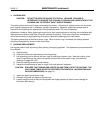
6. LEVELING OF THE UNIT
Lower the unit onto the foundation, positioning it so the anchor bolts are aligned with the center of the mounting
holes in the base. On all units, always disconnect the coupling halves and never reconnect them until all the
alignment operations are complete.
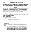
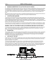
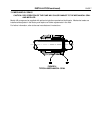
The base should be supported on metal shims or metal wedges placed directly under the part of the base
carrying the greatest weight, and spaced close enough to give uniform support and stability (see Figure 1).
Adjust the metal shims or wedges until the shafts of the pump and driver are level. Alignment adjustments can
be accomplished by adjusting the supports under the base. When proper alignment is obtained, tighten the
foundation bolts snugly, but not too firmly, and recheck the alignment before grouting.
Figure 1
BASEPLATE INSTALLATION