


MAINTENANCE (continued) PAGE 13
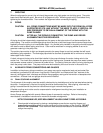
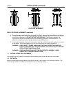
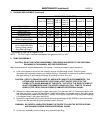
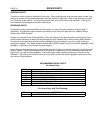
5. PACKING REPLACEMENT (continued)
PUMP MODEL
(
PUMP SIZE
)
5-442-18
6-442-15
6-442-18
8-442-15
PACKING BOX
Sleeve O.D. 1-3/4 1-7/8 2-1/2 2-1/2 3 3 3-7/8
Packing Box I.D. 2-1/2 2-5/8 3-1/2 3-1/2 4 4 5-1/8
Packing Box Depth 2-13/16 3-1/4 4-1/8 4 4 1/8 4 1/8 5-9/16
PACKING SIZE 3/8 3/8 1/2 1/2 1/2 3/4 5/8
Qty. of Rings per Box
(Without Lantern Ring)
Lantern Ring Width 3/4 3/4 1 1 1 1 1-1/4
PACKING ARRANGEMENT
WITH LANTERN RING
(Packing Rings-Lantern
Ring-Packing Rings)*
2-L-3 3-L-3 2-L-3 3-L-42-L-3 2-L-3 3-L-3
787 9777
4-442-10
4-442-14
4-442-18
3-442-10A
5-442-10
6-442-10
8-442-248-442-18 10-442-18
* See Sectional Drawings on pages 22 & 23.
NOTE: For Fire Pumps, the Model designation changes from “442” to “492.”
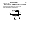
6. PUMP DISASSEMBLY
CAUTION: READ THIS ENTIRE DISASSEMBLY PROCEDURE AND REFER TO THE SECTIONAL
DRAWINGS IN THIS MANUAL BEFORE PROCEEDING.
Major maintenance will require disassembly of the pump. Following are step-by-step instructions.
A. Lock out the power to the driver and close the suction and discharge valves. Drain the pump,
disconnect and remove the coupling or flexible shafting. Disconnect and remove all auxiliary piping to
the upper casing (3) and bearing housings (6) (packing box flush line, etc.).
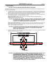
CAUTION: USE OF A CRANE OR HOIST OF ADEQUATE CAPACITY IS RECOMMENDED. THE
LIFTING HOOK SHOULD BE NO LESS THAN 3-4 FEET ABOVE THE EYE OF THE
EYEBOLTS TO AVOID BENDING OF THE BOLTS. THE USE OF THE SHORT EYEBOLTS
IS NOT RECOMMENDED SINCE THE UPPER CASING HALF WILL TEND TO TIP WHILE
BEING LIFTED, RESULTING IN POSSIBLE DAMAGE OR PERSONAL INJURY.
B. Remove the capscrews securing the upper casing half (3) to the lower half (2). Remove the gland nuts
and slide the glands (19) off the gland studs. Install jack screws in the tapped holes in the upper casing
half and use them to separate the flanges. Carefully lift the upper casing half using long shank eyebolts
in the tapped holes in the upper casing half.
C. Remove the capscrews and pins that secure the bearing cartridges (A158 & B158) to the lower casing.
The pins may be removed using the threaded holes in the pins.
WARNING: BE CAREFUL WHEN POSITIONING THE ROPES TO AVOID THE ROTOR SLIPPING
AND CAUSING POSSIBLE SERIOUS PERSONAL INJURY.
D. Lift the rotor assembly from the casing using a double rope sling.