65InRoom Precision AC Tech Data Manual
Guidelines for Installation
Room preparation
During the design of the room, consideration should be given to the following factors: ease of entry for the
system, floor-loading factors, and accessibility of piping and wiring.
The room must be sealed with a vapor barrier to minimize migration of moisture. Polyethylene film (plastic
sheeting) is a good vapor barrier for ceiling and wall applications. Rubber- or plastic-based paints should be
applied to concrete floors and walls. The room should be thoroughly insulated to minimize thermal loads and
make-up air (if required) should be preconditioned to reduce additional temperature, filtration, and moisture
loads.
A room using a raised-floor plenum for air distribution should have a finished floor height no less than
(305 mm) 12 in. The area under the floor should be free from obstructions. Pay special attention to the location
of pipe chases, electrical conduits and other obstructions under the floor. These objects can block air
circulation and cause loss of air pressure, thus reducing system efficiency and causing hot spots in the room.
Unit location
The location of the unit is important for efficient and balanced environmental control in the room. Contact an
APC representative for assistance in locating equipment in the room. If poorly installed, erratic control or
mechanical failure can result.
Service access
At least 1 meter (39 in) of clear space must be left in front of the unit for routine service (filters, humidifier).
Downflow units with a ducted return should have a field-installed access panel to allow for filter replacement.
Receiving the unit
The unit has been completely tested and inspected prior to shipment. To ensure that the unit received is in
excellent condition, perform a careful inspection of the crating and the unit immediately upon receipt. Verify
that all parts ordered were received as specified and that the unit is the correct size and voltage necessary to
fulfill the environmental control needs. Report any damage discovered to the freight carrier. If necessary,
contact the APC field service department for help in repairing or replacing damaged parts. While APC is not
responsible for damage incurred in transit, APC will work with you to make sure that there are no undue delays
in the system start-up.
Rigging
The unit is manufactured with a formed steel frame for maximum strength and unit integrity. However, as with
all electrical and mechanical equipment, take care with proper rigging of the unit.
When using a forklift to move the unit, use the shipping skid to protect the bottom of the unit. When hoisting
the unit from above, use spreader bars to prevent damage to the unit.
Floorstand
Follow the directions provided with the floorstand for proper installation.
Utility connections
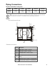
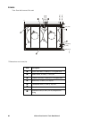
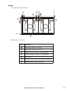
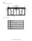
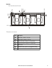
All connections are made through the bottom left of the unit (the left side of upflow discharge units) for ease of
service connections. See the installation manual for pipe sizes and specific locations for the unit.
Power to the unit
The unit uses 3-phase power for operation. Power connections are routed through the bottom of the unit.


