


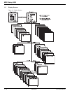
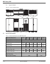
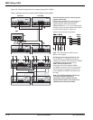
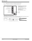
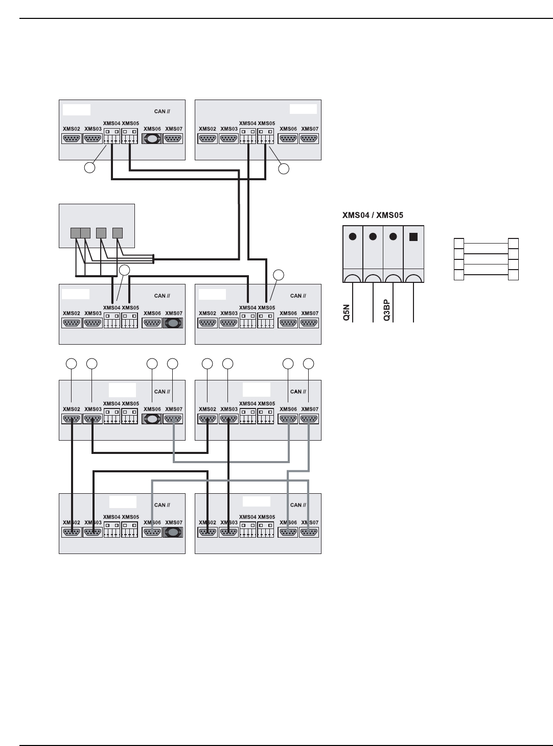
Figure 2-8: Parallel Configuration for Increased Capacity (Four UPSs)
These configurations have an external System Bypass Cabinet (SBC).
UPS 2
UPS 1
UPS 4
UPS 3
Blue
plug
Red
plug
no
m
mo
C
UPS 1
SBC
TB2
UPS 2
UPS 4
UPS 3
Blue
plug
Red plug
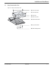
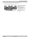
Interconnections with the external system
bypass cabinet (20):
◗ Interconnect terminals 7, 8, 9, and 10 on the
auxiliary terminal block TB2 in the system
bypass cabinet to UPS terminal blocks
XMS04/XMS05 pins 1, 2, 3, and 4 respectively.
◗ Create a loop connection between the cabinet
and the UPSs as shown in Figure 2-8.
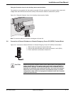
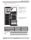
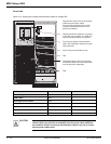
Details of terminal block connections.
Note: The interconnection cables for the
SBC are not supplied
Note: The supplied cables are 33 ft long.
To ensure sufficient isolation of
exchange-current, CAN and external
bypass cabinet cables, they must be run
separately from the power cables.
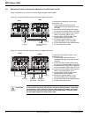
Exchange-current interconnections (19):
Use the XMS02 and XMS03 connectors to
create a loop between the UPSs (all the XMS02
and XMS03 connectors must be used).
CAN // interconnections (21):
Daisy-chain the UPSs using the XMS06
and XMS07 connectors. Fit a blue plug on the
first UPS unit and a red plug on the last UPS
(all the XMS06 and XMS07 connectors must
be used).
78
9
8
7
10
3
2
1
4
910
PCA INTN
19 19 19 19
20
20
TB2
4321
20
20
21 21 21 21
PCA INTN
9
8
7
10
3
2
1
4
SBC
XMS04 /
XMS05
MGE Galaxy 5000
Setup and Installation2 — 6 86-174010-00 B00