


46 McQuay OM 751
Diagnostics and Service
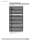
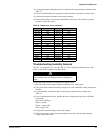
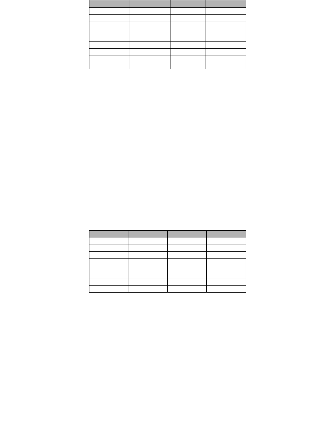
Table 24: Humidity versus voltage.
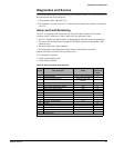
Troubleshooting Carbon Dioxide (CO
2
) Sensors
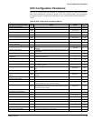
The UVC is configured to use a 0–2000 PPM, 0–10 VDC, single beam absorption infrared gas
sensor. Each sensor is calibrated according to the table shown.
Use the following procedure to troubleshoot a suspect sensor.
1 Disconnect the sensors output voltage lead from the UVC analog input (xAI-3).
2 Using some other calibrated CO
2
sensing device, take a CO
2
reading at the sensor location.
3 Use the CO
2
reading from Step 2 to determine the expected sensor voltage from Table 25.
4 Using a calibrated multi-meter, measure the actual voltage across the lead removed from
xAI-3 and ground.
5 Compare the expected voltage to the actual voltage.
6 If the actual voltage value deviates substantially (more than 10%) from the expected
voltage, replace the sensor.
In the unlikely event that the CO
2
sensor requires calibration, consult the factory for
information on obtaining calibration equipment and instructions.
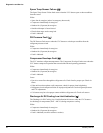
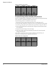
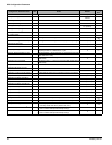
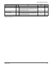
Table 25: CO
2
versus voltage table
RH (%) VDC (mV) RH (%) VDC (mV)
10 1330 55 2480
15 1475 60 2600
20 1610 65 2730
25 1740 70 2860
30 1870 75 2980
35 1995 80 3115
40 2120 85 3250
45 2235 90 3390
50 2360 95 3530
CO
2
(PPM) VDC (V) CO
2
(PPM) VDC (V)
300 1.5 1200 6.0
400 2.0 1300 6.5
500 2.5 1400 7.0
600 3.0 1500 7.5
700 3.5 1600 8.0
800 4.0 1700 8.5
900 4.5 1800 9.0
1000 5.0 1900 9.5