


McQuay OM 751 41
Diagnostics and Service
Diagnostics and Service
The most important aspect of troubleshooting unit ventilator controls is to isolate the source of
the problem into one of two categories:
1 The problem resides within the UVC.
2 The problem is external to the UVC. Under most circumstances the problem is external to
the UVC.
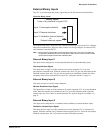
Alarm and Fault Monitoring
The UVC is programmed to monitor the unit for specific alarm conditions. If an alarm
condition exists, a fault occurs. When a fault exists, the following occurs:
• The UVC indicates the fault condition by displaying the fault code on the keypad/display.
• The remote wall-mounted sensor (optional) LED flashes a pattern indicating that a fault
condition exists.
• The fault signal binary output energizes.
• The fault performs the appropriate control actions as described for each fault.
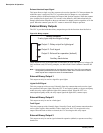
Manual reset faults can be reset in one of three ways:
• By cycling the unit power.
• Via the keypad/display menu.
• Via the network interface.
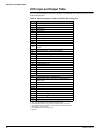
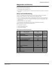
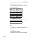
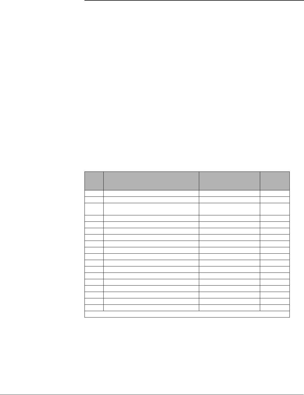
Table 22: Alarm and fault code summary
Priority Fault description Reset
Keypad/
display fault
codes
1 Space Temp Sensor Failure Auto
F0
2 DX Pressure Fault 2-Auto in 7 days, then Manual
F1
3
Compressor Envelope Fault 2-Auto in 7 days, then
Manual*
F2
4 Discharge Air DX Cooling Low Limit Indication Auto
F3
5 Condensate Overflow Indication Auto
F4
6 Space Coil DX Temp Sensor Failure Auto
F5
7 Outdoor Temp Sensor Failure Auto
F6
8 Discharge Air Temp Sensor Failure Auto
F7
9 Water Coil DX Temp Sensor Failure Auto
F8
10 Water-out Temp Sensor Failure Auto
F9
11 Space Humidity Sensor Failure Auto
FA
12 Outdoor Humidity Sensor Failure Auto
Fb
13 Space CO
2
Sensor Failure Auto
FC
14 Not used
Fd
15 Not used
FE
16 Change Filter Indication Manual
FF
17 EPROM Memory Indicator Replace conroller board
EE
18 Configuration Display Download file
--
* Rev 1_27 has auto reset