


McQuay OM 751 45
Diagnostics and Service
3
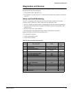
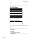
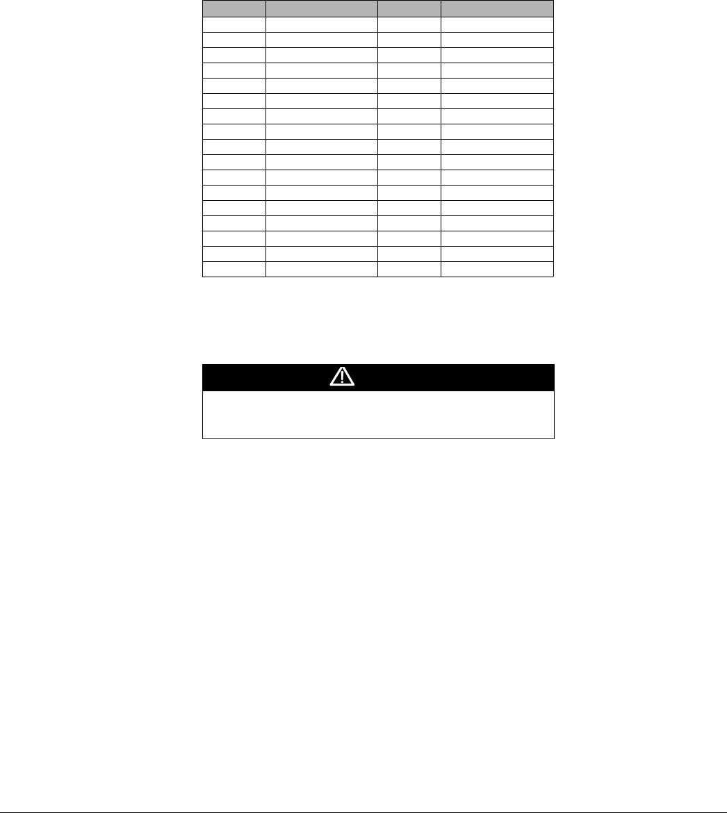
Use the temperature reading from Step 2 to determine the expected sensor resistance from
Table 23.
4 Using a calibrated ohmmeter, measure the actual resistance across the two sensor leads.
5 Compare the expected resistance to the actual resistance.
6 If the actual resistance value deviates substantially (more than 10%) from the expected
resistance, replace the sensor.
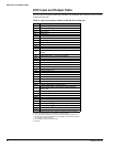
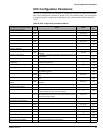
Table 23: Temperature versus resistance
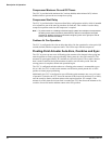
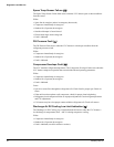
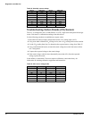
Troubleshooting Humidity Sensors
The UVC is configured to use a 0–100% RH, 0–5 VDC, capacitive humidity sensor. Each
sensor is calibrated according to the table shown.
Use the following procedure to troubleshoot a suspect sensor:
1 Disconnect the sensors output voltage lead from the UVC analog input.
2 Using some other calibrated humidity sensing device, take a humidity reading at the sensor
location.
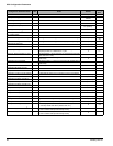
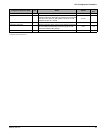
3 Use the humidity reading from Step 2 determine the expected sensor voltage from
Table 24.
4 Using a calibrated multi-meter, measure the actual voltage across the yellow and white
sensor leads.
Wire color definitions:
White = ground
Yellow = output VDC
Blue = supply VDC
5 Compare the expected voltage to the actual voltage.
6 If the actual voltage value deviates substantially (more than 10%) from the expected
voltage, replace the sensor.
°F (°C) Resistance in ohms °F (°C) Resistance in ohms
–40 (–40) 613 113 (45) 1195
–31 (–35) 640 122 (50) 1237
–22 (–30) 668 131 (55) 1279
–13 (–25) 697 140 (60) 1323
–4 (–20) 727 149 (65) 1368
5 (–15) 758 158 (70) 1413
14 (–10) 789 167 (75) 1459
23 (–5) 822 176 (80) 1506
32 (0) 855 185 (85) 1554
41 (5) 889 194 (90) 1602
50 (10) 924 203 (95) 1652
59 (15) 960 212 (100) 1702
68 (20) 997 221 (105) 1753
77 (25) 1035 230 (110) 1804
86 (30) 1074 239 (115) 1856
95 (35) 1113 248 (120) 1908
104 (40) 1153
CAUTION
The humidity sensor is not protected against reversed polarity.
Check carefully when connecting the device or damage can
result.