


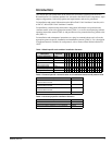
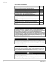

Introduction. . . . . . . . . . . . . . . . . . . . . . . . . . . . . . . . 3
Acronyms/Abbreviations . . . . . . . . . . . . . . . . . . . . . . . . . . . . . . . . . .5
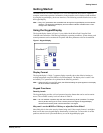
Getting Started . . . . . . . . . . . . . . . . . . . . . . . . . . . . . 7
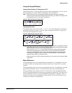
Using the Keypad/Display. . . . . . . . . . . . . . . . . . . . . . . . . . . . . . . . .7
Display Format . . . . . . . . . . . . . . . . . . . . . . . . . . . . . . . . . . . . .7
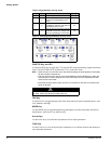
Keypad Functions . . . . . . . . . . . . . . . . . . . . . . . . . . . . . . . . . . .7
Using the Keypad/Display. . . . . . . . . . . . . . . . . . . . . . . . . . . . .9
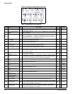
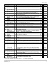
Menu Reference . . . . . . . . . . . . . . . . . . . . . . . . . . . . . . . . . . . .9
Description of Operation . . . . . . . . . . . . . . . . . . . . 12
State Programming . . . . . . . . . . . . . . . . . . . . . . . . . . . . . . . . . . . . .12
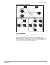
UVC Unit Modes . . . . . . . . . . . . . . . . . . . . . . . . . . . . . . . . . . . . . . .13
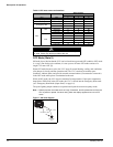
OFF Mode (State 9) . . . . . . . . . . . . . . . . . . . . . . . . . . . . . . . .14
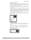
Night Purge Mode (State 8) . . . . . . . . . . . . . . . . . . . . . . . . . .15
Fan Only Mode (State A) . . . . . . . . . . . . . . . . . . . . . . . . . . . .15
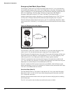
Emergency Heat Mode (Super State). . . . . . . . . . . . . . . . . . .16
Auto Mode. . . . . . . . . . . . . . . . . . . . . . . . . . . . . . . . . . . . . . . .17
Cool Mode (Super State) . . . . . . . . . . . . . . . . . . . . . . . . . . . .18
Special Purpose Unit Modes. . . . . . . . . . . . . . . . . . . . . . . . . .21
Unit Mode Priority . . . . . . . . . . . . . . . . . . . . . . . . . . . . . . . . . . . . . .23
Occupancy Modes. . . . . . . . . . . . . . . . . . . . . . . . . . . . . . . . . . . . . .24
Occupied Mode. . . . . . . . . . . . . . . . . . . . . . . . . . . . . . . . . . . .24
Unoccupied Mode . . . . . . . . . . . . . . . . . . . . . . . . . . . . . . . . . .24
Standby Mode. . . . . . . . . . . . . . . . . . . . . . . . . . . . . . . . . . . . .24
Bypass Mode . . . . . . . . . . . . . . . . . . . . . . . . . . . . . . . . . . . . .25
Additional Occupancy Features . . . . . . . . . . . . . . . . . . . . . . . . . . .25
Networked Occupancy Sensor Capability. . . . . . . . . . . . . . . .25
Unit-Mounted Time-Clock . . . . . . . . . . . . . . . . . . . . . . . . . . . .25
Unit-Mounted Tenant Override Switch . . . . . . . . . . . . . . . . . .25
Remote Wall-Mounted Sensor Tenant Override Switch . . . . .25
Remote Wall-Mounted Sensor Status LED. . . . . . . . . . . . . . .25
Space Temperature Set Points. . . . . . . . . . . . . . . . . . . . . . . . . . . .26
Networked Set Point Capability. . . . . . . . . . . . . . . . . . . . . . . .26
Networked Set Point Offset Capability . . . . . . . . . . . . . . . . . .26
Networked Set Point Shift Capability . . . . . . . . . . . . . . . . . . .26
Networked Space Temperature Sensor Capability. . . . . . . . .26
Remote Wall-Mounted Sensor with +/–3°F
Adjustment (optional) . . . . . . . . . . . . . . . . . . . . . . . . . . .27
Remote Wall-Mounted Sensor with 55°F to 85°F
Adjustment (optional) . . . . . . . . . . . . . . . . . . . . . . . . . . .27
Effective Set Point Calculations . . . . . . . . . . . . . . . . . . . . . . .27
Proportional Integral (PI) Control Loops . . . . . . . . . . . . . . . . . . . . .29
Discharge Air Temperature Control . . . . . . . . . . . . . . . . . . . .29
PI Control Parameters. . . . . . . . . . . . . . . . . . . . . . . . . . . . . . . . . . .30
Proportional Band . . . . . . . . . . . . . . . . . . . . . . . . . . . . . . . . . .30
Integral Time . . . . . . . . . . . . . . . . . . . . . . . . . . . . . . . . . . . . . .31
Indoor Air Fan Operation. . . . . . . . . . . . . . . . . . . . . . . . . . . . . . . . .31
Auto Mode. . . . . . . . . . . . . . . . . . . . . . . . . . . . . . . . . . . . . . . .31
Occupied, Standby, and Bypass Operation . . . . . . . . . . . . . .31
Unoccupied Operation . . . . . . . . . . . . . . . . . . . . . . . . . . . . . .32
Cycle Fan. . . . . . . . . . . . . . . . . . . . . . . . . . . . . . . . . . . . . . . . 32
Off Delay . . . . . . . . . . . . . . . . . . . . . . . . . . . . . . . . . . . . . . . . 32
Outdoor Air Damper Operation . . . . . . . . . . . . . . . . . . . . . . . . . . . 32
Minimum Position . . . . . . . . . . . . . . . . . . . . . . . . . . . . . . . . . 32
Economizer Operation. . . . . . . . . . . . . . . . . . . . . . . . . . . . . . 32
Networked Space Humidity Sensor Capability . . . . . . . . . . . 34
Networked Outdoor Humidity Sensor Capability . . . . . . . . . . 34
CO
2
Demand Controlled Ventilation (optional) . . . . . . . . . . . 34
Networked Space CO
2
Sensor Capability. . . . . . . . . . . . . . . 34
ASHRAE Cycle II. . . . . . . . . . . . . . . . . . . . . . . . . . . . . . . . . . 35
Compressor Operation . . . . . . . . . . . . . . . . . . . . . . . . . . . . . . . . . 35
Compressor Envelope. . . . . . . . . . . . . . . . . . . . . . . . . . . . . . 35
Compressor Cooling Lockout . . . . . . . . . . . . . . . . . . . . . . . . 35
Compressor Minimum On and Off Timers. . . . . . . . . . . . . . . 36
Compressor Start Delay . . . . . . . . . . . . . . . . . . . . . . . . . . . . 36
Outdoor Air Fan Operation . . . . . . . . . . . . . . . . . . . . . . . . . . 36
Floating-Point Actuator Auto-Zero, Overdrive and Sync . . . . . . . . 36
External Binary Inputs . . . . . . . . . . . . . . . . . . . . . . . . . . . . . . . . . . 37
External Binary Input 1 . . . . . . . . . . . . . . . . . . . . . . . . . . . . . 37
External Binary Input 2 . . . . . . . . . . . . . . . . . . . . . . . . . . . . . 37
External Binary Input 3 . . . . . . . . . . . . . . . . . . . . . . . . . . . . . 37
External Binary Outputs. . . . . . . . . . . . . . . . . . . . . . . . . . . . . . . . . 38
External Binary Output 1 . . . . . . . . . . . . . . . . . . . . . . . . . . . . 38
External Binary Output 2 . . . . . . . . . . . . . . . . . . . . . . . . . . . . 38
External Binary Output 3 . . . . . . . . . . . . . . . . . . . . . . . . . . . . 38
UVC Input and Output Table . . . . . . . . . . . . . . . . . 40
Diagnostics and Service. . . . . . . . . . . . . . . . . . . . . 41
Alarm and Fault Monitoring . . . . . . . . . . . . . . . . . . . . . . . . . . . . . . 41
Space Temp Sensor Failure (F0). . . . . . . . . . . . . . . . . . . . . . 42
DX Pressure Fault (F1) . . . . . . . . . . . . . . . . . . . . . . . . . . . . . 42
Compressor Envelope Fault (F2). . . . . . . . . . . . . . . . . . . . . . 42
Discharge Air DX Cooling Low Limit Indication (F3) . . . . . . . 42
Condensate Overflow Indication (optional) (F4). . . . . . . . . . . 43
Space Coil DX Temp Sensor Failure (F5) . . . . . . . . . . . . . . . 43
Outdoor Temp Sensor Failure (F6) . . . . . . . . . . . . . . . . . . . . 43
Discharge Air Temp Sensor Failure (F7) . . . . . . . . . . . . . . . . 43
Outdoor Coil DX Temp Sensor Failure (F8). . . . . . . . . . . . . . 43
Space Humidity Sensor Failure (optional) (FA) . . . . . . . . . . . 44
Outdoor Humidity Sensor Failure (optional) (Fb) . . . . . . . . . . 44
Space CO2 Sensor Failure (optional) (FC). . . . . . . . . . . . . . . 44
Change Filter Indication (FF) . . . . . . . . . . . . . . . . . . . . . . . . . 44
EPROM Memory Indicator (EE) . . . . . . . . . . . . . . . . . . . . . . . 44
Configuration Display (--) . . . . . . . . . . . . . . . . . . . . . . . . . . . 44
Troubleshooting Temperature Sensors . . . . . . . . . . . . . . . . . . . . . 44
Troubleshooting Humidity Sensors . . . . . . . . . . . . . . . . . . . . . . . . 45
Troubleshooting Carbon Dioxide (CO
2
) Sensors. . . . . . . . . . . . . . 46
UVC Configuration Parameters . . . . . . . . . . . . . . . 47