


McQuay OM 751 11
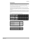
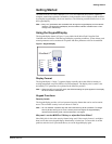
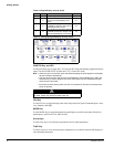
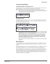
Getting Started
o5
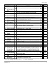
Exhaust Interlock OAD
Min Position set point
EOAD
Adjust OA damper position above which the exhaust fan output will be energized.
There is a fixed –5% differential associated with this set point.
RW x 99%
o6
Energize Exhaust Fan
OAD Set point
OADE
Adjust OA damper minimum position when the exhaust interlock input is
energized.
RW x 12%
o7
OAD Max Position Set
point
OAMX Adjust OA damper maximum position. RW x 99%
o8
OAD Lockout Enable
Set OA damper lockout feature status: 0 = disable, 1 = enable. (This variable is
factory set to 1 when the unit is ordered as a recirc unit with no OAD.)
RW x 0
o9
OAD Lockout Set point OALS
Adjust OA temperature below which the OA damper closes if the OA damper
lockout is enabled. (This variable is factory set to –99
°
C when the unit is ordered
as a recirc unit with no OAD.)
RW x
35.6°F
(2°C)
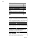
E1
Economizer Enable Set economizer status: 0 = disable, 1 = enable. RW x 1
E2
Economizer OA Temp
Set point
ETS
Adjust economizer OA temperature set point. DO NOT lower this set point below
CCLO or you risk creating a deadband where no cooling occurs.
RW x
68°F
(20°C)
E3
Economizer IA/OA Temp
Differential
ETD Adjust economizer IA/OA temperature differential. RW x 1.8°F (1°C)
E5
Economizer OA Enthalpy
Set point
EES Adjust economizer OA enthalpy set point. RW x
25 Btu/lb
(58 kJ/kg)
E6
Economizer IA/OA
Enthalpy Differential
EED Adjust economizer IA/OA enthalpy differential. RW x
1.3 Btu/lb
(3 kJ/kg)
r1
Space Humidity Output ERH Display room humidity (optional). 00 = No sensor connected. RO x
r3
Outdoor Air Humidity
Output
EORH Display OA humidity (optional). 00 = No sensor connected. RO x
ot
Outdoor Air Temp Output EOAT Display OA temperature. RO x
k1
Emergency Heat Enable Set emergency heat status: 0 = disable, 1 = enable. RW x 1
k2
Emergency Heat Set
point
EHS Adjust emergency heat set point. RW x
53.6°F
(12°C)
k3
Emergency Heat
Shutdown Configuration
Set emergency heat operation during shutdown, 0 = no emergency heat during
shutdown: 1 = allow emergency heat during shutdown.
RW x 0
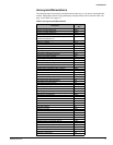
A1
Auxiliary Heat Start
Differential
AHSD Adjust auxiliary heat start differential. RW x 1.8°F (1°C)
A2
Auxiliary Heat End
Differential
AHED Adjust auxiliary heat stop differential. RW x 1.8°F (1°C)
A3
Auxiliary Heat
Configuration
Set auxiliary heat type: 0 = N.O. device, 1 = N.C. device. RW x 0
b3
External BI-3
Configuration
Set the function external binary Input 3: 0 = ventilation lockout, 1 = exhaust
interlock.
RW x 0
b6
External BO-3
Configuration
Set the function of external binary output 3: 0 = exhaust fan on/off signal, 1 =
auxiliary heat.
RW x 0
(F
Fan Cycling
Configuration
Set space fan cycles (switches off) during occupied, bypass, and standby mode: 2
= continuous, 3 = cycling.
RW x 2
(E
Filter Alarm Enable Set filter alarm status: 0 = disable, 1 = enable. RW x 0
(r
Reset Filter Alarm Input Enter 1 to clear filter alarm. RW x
//
2
(1
Compressor Enable Set compressor status: 0 = disable, 1 = enable. RW x 1
(2
Compressor Cooling
Lockout Set point
CCLO
Adjust compressor cooling lockout set point. When the OA temperature falls below
this set point, compressor cooling is not allowed. DO NOT make this setting lower
than the factory default. There is a fixed +3.6°F (2°C) differential associated with
this set point.
RW x
63.5°F
(17.5°C)
(3
Compressor Heating
Lockout Set point
CHLO
Adjust compressor heating lockout set point. When the OA temperature falls below
this set point, compressor heating is not allowed and only electric heat will be used.
RW x
25°F
(-4°C)
(6
Compressor Start Delay
Adjust compressor start delay. Where several units (inductive loads) are
connected to the same electrical supply, make this set point unique for every UVC
to prevent multiple compressors from energizing at the same time after a power
failure or occupancy change.
RW x 0 sec
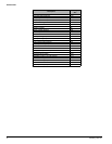
SP
Space Temp Sensor
Offset
Adjust this setting to bias the UVC measured space temperature. RW x 0
Un
Keypad/display
Temperature Units
Set keypad/display temperature units in English or SI. This set point also effects
which unit types displayed over Metasys N2 and BACnet MS/TP networks using
the appropriate optional communications modules.
RW x F
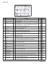
1. RW = read and write capable, RO = read only.
2. If a menu value is greater than 2-digits (higher than 99), then
// will be displayed on the keypad/display.
Display Keypad menu item list Abr. Description
RO
RW
1
05
Default