


40 McQuay OM 751
UVC Input and Output Table
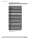
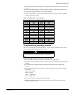
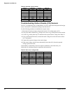
UVC Input and Output Table
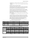
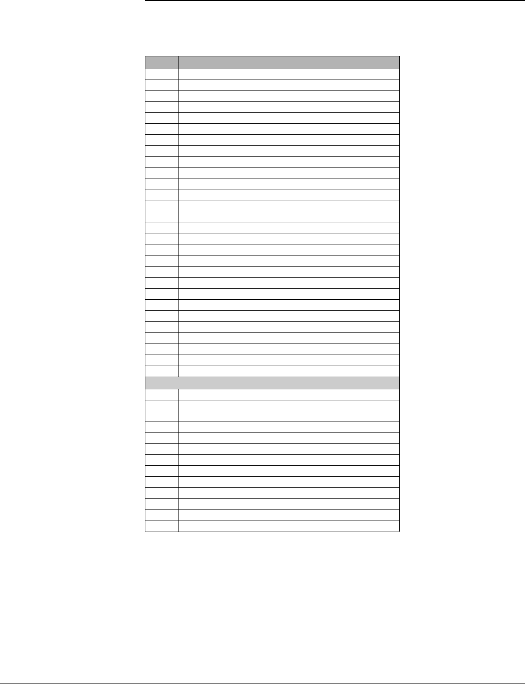
All UVC input and output connections and their corresponding unit ventilator usage are shown
in the following table.
Table 21: Inputs and outputs, software model 05—DX cooling only
I/O Description
BO-1 Inside Fan High
BO-2 Inside Fan Medium
BO-3 Electric Heat 1
BO-4 Electric Heat 2
BO-5 Electric Heat 3
BO-6 External Output Option 2: Fault Indication
1
1. Field selectable external output options (all possible options are shown).
BO-7
BO-8
BO-9 Compressor
2
2. This is the condensing unit on/off signal on split-systems.
BI-1 Condensate Overflow
BI-2
BI-3
BI-4
External Input Option 3:Ventilation Lockout (default) or Exhaust
Interlock
3
3. Field selectable external input options (all possible options are shown).
BI-5 External Input Option 2: Remote Shutdown
3
BI-6 External Input Option 1: Unoccupied (default)
BI-7
BI-8
BI-9
BI-10
BI-11
BI-12 DX Press Switch (NC)
4
4. DX pressures switch not installed on split-systems; this input is then wired
for constant no-fault condition.
AI-1 IA Temp. Sensor + T.O.
AI-2 Remote Setpt. Adjust. Pot.
AI-3 OA Coil DX Temp Sensor
5
5. Not installed or wired on split-systems.
AI-4 OA Temp Sensor
AI-5 IA Coil DX Temp Sensor
AI-6 DA Temp Sensor
Expansion board
xBO-1 External Output Option 1: Lights On/Off
1
xBO-2
External Output Option 3: Exhaust Fan On/Off (default) or
Auxiliary Heat
1
xBO-3 OA Damper Open
xBO-4 OA Damper Close
xBO-5
xBO-6
xBO-7 Outdoor Fan
5
xBO-8 Inside Fan Low
xAI-1 IA Humidity Sensor
6
6. Optional.
xAI-2 OA Humidity Sensor
6
xAI-3 Indoor CO
2
Sensor
6
xAI-4