


USER MANUAL
ENGLISH
RS 850 33014576(4)2008-02 A
41
SUCTION INLET DISASSEMBLY/ASSEMBLY
NOTE
This is a basic procedure, it is often recalled during other procedures, when necessary.
Disassembly
Remove the side brooms (see the procedure in the relevant paragraph).
Move the 3rd broom (21, Fig. G) aside, and lower the suction inlet (17) according to the procedure shown in the relevant
paragraph.
Engage the parking brake (13, Fig. E).
Turn the ignition key (24, Fig. D) to OFF position and remove it.
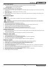
Mark the position of the pipes (1 and 2, Fig. AY) (for proper assembly), then disconnect them from the suction inlet (3) and plug
them.
Mark the position of the pipes (4 and 5, Fig. AY) (for proper assembly), then disconnect them from the suction inlet (3) and plug
them.
Disconnect the dust control system pipes (6 and 7, Fig. AY).
Disconnect the electrical connectors (8 and 9, Fig. AY) and remove the gasket.
Remove the screws (10, Fig. AY).
Move the suction inlet (3, Fig. AY) forward, and loosen the suction pipe clamp (11).
Disconnect the suction pipe (12, Fig. AY) from the suction inlet.
On both sides of the suction inlet, unscrew the nuts (13, Fig. AY) and disconnect the relevant springs.
Remove the suction inlet (3).
Collect the pipes (15, Fig. AY) disconnected from the suction inlet, and secure them with clamps (14).
Fit a dust boot to prevent dirt and foreign material from entering the pipes (15).
Assembly
Assemble the components in the reverse order of disassembly.
If necessary, check the suction inlet and skirt height and operation (see the procedure in the relevant paragraph).
3RD BROOM ARM DISASSEMBLY/ASSEMBLY
NOTE
This is a basic procedure, it is often recalled during other procedures, when necessary.
CAUTION!
This procedure is applicable only for sweepers with appropriate fi ttings for installation of snow brush.
Disassembly
Extend the 3rd broom arm (23, Fig. G) and lift the broom (21) according to the procedure shown in the relevant paragraph.
Turn off the engine and engage the parking brake (13, Fig. E).
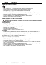
Operating according to the safety rules, with a proper hoisting system (1, Fig. AZ), sling the 3rd broom arm (2) in the points
shown in the fi gure. Move the pipes and cable aside, to avoid squashing them during the lifting operation.
3rd broom arm weight: approximately 176.4 (80 kg).
Disconnect the electrical connector (3, Fig. AZ).
Disconnect the hydraulic system quick couplings (4, Fig. AZ) from the corresponding pipe couplings (5), then install the
protection covers.
Disconnect the dust control system quick coupling (6, Fig. AZ) from the corresponding pipe coupling (7), then install the
protection covers.
Inside the cab, remove the screw (8, Fig. AZ), then remove the panel (9).
Slightly tighten the hoisting system (1, Fig. AZ), then remove the screws (10) and the nut (11).
Remove the 3rd broom arm (2, Fig. AZ).
Assembly
Assemble the components in the reverse order of disassembly.
If necessary, check and adjust the 3rd broom position (see the procedure in the relevant paragraph).
1.
2.
3.
4.
5.
6.
7.
8.
9.
10.
11.
12.
13.
14.
15.
16.
1.
2.
3.
4.
5.
6.
7.
8.
9.
10.
11.