


29
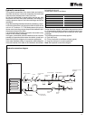
Fig. 1
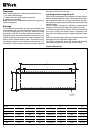
Fig. 2
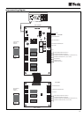
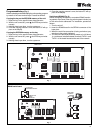
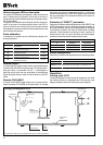
Programmable key (Fig. 1)
Allows uploading and downloading the unit operating program
by means of the user terminal keys. Proceed as follows:
Copying the key on the EEPROM memory of the unit
1.- Insert the key in the specific base plate connector.
2.- With the unit turned off, press and PRG keys simulta-
neously.
3.- Holding these keys down, turn the system on.
4.- Once the copying process is over, the letters CE will ap-
pear on the display.
Copying the EEPROM memory on the key
1.- Insert the key in the specific base plate connector.
2.- With the unit turned off, press and PRG keys simulta-
neously.
3.- Holding these keys down, turn the system on.
4.- Once the copying process is over, the letters EC will ap-
pear on the display.
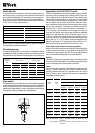
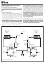
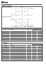
Serial board RS485 (Fig. 2)
Allows connecting the system to a standard RS485 monitor-
ing network. By means of the clip-switch system included, up
to 199 units can be addressed. For installation, proceed as
follows:
1.- Turn the unit off.
2.- Insert the RS485 board in the SERIAL connector of the
base plate.
3.- When the serial line connection is being carried out, pay
attention to the polarity indicated.
4.- The serial line should be closed by means of a 120 ohms
¼ w resistance installed between terminals TX/RX + and
TX/RX - of the board located at the end of the network.
µ
P
SERIAL
GND Y1
KEY
G GO GND B1 GND B2 GND B3 24V
BASE PLATE
IDCOM ID1 ID2 ID3 ID4 ID5 ID6 ID7
P6
NO C NO C NC NO C
RES.1 COMP.1 VALVE 1 PUMP ALARM
KEY
NO C NO C NC
1-2= NTC
2-3=ON/OFF
B1 B2 B4
1-2= NTC
2-3= 4-20mA
B3 B5
P5P4P3P2
3
P1
2
1
µ
P
RS485 SERIAL
CONVERTER
120 W
SERIAL
GND Y1
KEY
G GO GND B1 GND B2 GND B3 24V IDCOM ID1 ID2 ID3 ID4 ID5 ID6 ID7
P6
NO C NO C NC NO C
RES.1 COMP.1 VALVE 1 PUMP ALARM
TO BASE PLATE
"SERIAL"
CONNECTOR
TO THE RS485
MONITORING NETWORK
GND
TxRxTxRx
ON OFF
4
3
2
1
NO C NO C NC
1-2= NTC
2-3=ON/OFF
B1 B2 B4
1-2= NTC
2-3= 4-20mA
B3 B5
P5P4P3P2
3
P1
2
1
RS485 serial board