


22
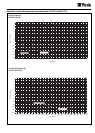
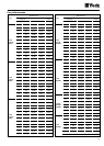
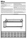
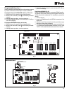
Model A B C D E F Ø G
42 2 240 774 200 1 840 55 664 16.5 (4)
62 2 240 929 200 1 840 55 819 16.5 (4)
82 2 891 1 000 200 1 245.5 (x 2) 55 890 16.5 (6)
102 2 891 1 000 200 1 245.5 (x 2) 55 890 16.5 (6)
122 3 200 1 300 200 1 400 (x2) 55 1 190 16.5 (6)
152 3 200 1 300 200 1 400 (x2) 55 1 190 16.5 (6)
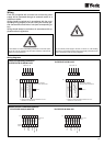
Clearances
When installing each unit, clearances should be left for:
1- Air intake and discharge.
2- Water, drain and power supply connections
3- Maintenance servicing.
Note: See minimum clearances indicated on the general di-
mensions diagrams.
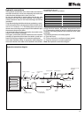
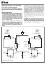
Drainage
The unit has two connections for draining condensed water
accumulated in the coil during operation in the winter cycle,
or for fully emptying the unit. The outer diameter of these
connections is 28 mm. At outdoor temperatures below 0° C,
condensed water can freeze and obstruct the drain. It is ad-
visable to take this into account and, when considered nec-
essary, install a flexible electric heater. This heater can be
connected by means of an ambient thermostat set to 3° C,
for example. This thermostat activates the heater when the
temperature is below the set point.
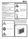
Locating and securing the unit
These units are designed to be placed on the floor indoors.
With air discharge and return ducts, if necessary. Before open-
ing the packing, make sure you have received the appropri-
ate product by checking the specifications described on the
outside of same.
The unit should be placed on a perfectly horizontal plane,
making sure the base can support the weight of the unit.
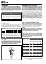
If vibration-free operation is required, the unit can be placed
on a cork or similar anti-vibratory base, or fastened to the
base with anti-vibratory plates or supports (optional acces-
sory).
If the unit is to be placed on the floor, a concrete base should
be prepared so as to distribute weight evenly.
The following illustration shows the spaces and fastening
points that correspond to the location of each model.
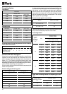
Location dimensions
ANCHORING
HOLES Ø G
B
A
CDC
E
E
F