


25
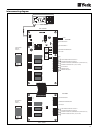
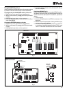
Wiring
Each unit is supplied with a control box to which the power
supply will be connected through an automatic switch or a
fused main switch.
Wiring should be carried out in accordance with the corre-
sponding wiring diagram of the unit, taking into account gen-
eral characteristics and limits of use (see corresponding ta-
ble).
Wiring should always be carried out in accordance with ap-
plicable national regulations.
Loose cables can cause overheating of terminals or incorrect opera-
tion of the unit. Fire hazards may also exist. Therefore, make sure all
cables are connected firmly.
Do not connect power supply to the unit, nor turn it on, until all tubing
and wiring is connected. Check correct power supply connection to the
units in accordance with the wiring diagrams.
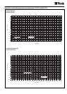
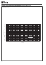
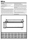
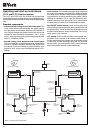
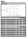
Wiring diagrams
400.3.50 + N
L1
L2
L3
N
R 1234567
FLOW SWITCH
VOLT-FREE CONTACT
WATER PUMP CONTACTOR
VOLT-FREE CONTACT
ALARM OUTLET
COOL/HEAT
ON/OFF
(*)
(*) REMOVE JUMPER BETWEEN TERMINALS R and 5.
CONNECT A FLOW SWITCH
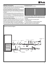
X2...
R B3412RX2...
1
234567
7 x 0.35 mm
2
Cable
Remote
control
24 VAC
ALARM
INTAKE
ON/OFF
COOL/HEAT
COMMON
Black
White
Violet
Yellow
Blue
Grey
Brown
R B3412BX2...
1
234567
7 x 0.35 mm
2
Cable
24 VAC
ALARM
INTAKE
ON/OFF
COOL/HEAT
COMMON
Black
White
Violet
Yellow
Blue
Grey
Brown
Power and operating connection
YLCC/YLCC-H 42, 62, 82 & 102
Remote control connection (optional)
YLCC/YLCC-H 42, 62, 82 & 102
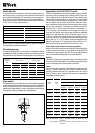
YLCC/YLCC-H 122 & 152
YLCC/YLCC-H 122 & 152
400.3.50 + N
L1
L2
L3
N
B 1234567
FLOW SWITCH
VOLT-FREE CONTACT
WATER PUMP CONTACTOR
VOLT-FREE CONTACT
ALARM OUTLET
COOL/HEAT
ON/OFF
(*)
(*) REMOVE JUMPER BETWEEN TERMINALS B and 5.
CONNECT A FLOW SWITCH
X2...