


28
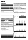
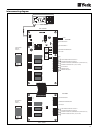
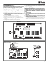
Terminals Description
B1-GND Water temp. probe at evaporating unit intake
B2-GND Water temp. probe at evaporating unit outlet (Circuit 1)
B3-GND Fan speed and circuit defrost control probe (Circuit 1)
B4-GND Evaporating unit water discharge temp. (Circuit 2)
B5-GND Fan speed and circuit defrost control probe (Circuit 2)
ID1-IDCOM High pressure switch (Circuit 1)
ID2-IDCOM Low pressure switch (Circuit 2)
ID3-IDCOM Compressor thermal protector (Circuit 1) (YLCC and YLCC-H - 82 and 102 only) (or fan on YLCC)
ID4-IDCOM Fan thermal protector (Circuit 1) (YLCC-H only)
ID5-IDCOM Water flow switch and auxiliary contact of pump contactor
ID6-IDCOM Remote ON/OFF
ID7-IDCOM Remote cool/heat
ID8-IDCOM High pressure switch (Circuit 2)
ID9-IDCOM Low pressure switch (Circuit 2)
ID10-IDCOM Compressor thermal protector (Circuit 2) (YLCC and YLCC-H - 82 and 102 only) (or fan on YLCC)
ID11-IDCOM Fan thermal protector (Circuit 2) (YLCC-H only)
Y1-GND PWM analogical outlet for fan control (Circuit 1)
Y2-GND PWM analogical outlet for fan control (Circuit 2)
RES. 1 Antifreeze or backup heater (Circuit 1)
COMP. 1 Compressor (Circuit 1)
VALVE 1 4-way valve (Circuit 1)
PUMP Water pump
ALARM General alarm remote signal
RES. 2 Antifreeze or backup heater (Circuit 2)
COMP. 2 Compressor (Circuit 2)
VALVE 2 4-way valve (Circuit 2)
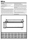
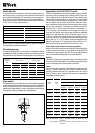
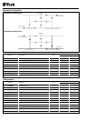
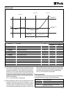
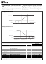
Identification of system intakes and outlets
Accessories
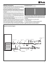
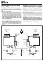
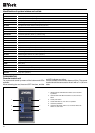
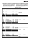
Remote control unit
For access and control by means of the buttons and LEDs
available.
Allows selecting the cool, heat and OFF functions, and the
red LED indicates any failure.
Can be installed at a maximum distance of 50 m. The remote
terminal should be connected to the unit with a 7 x 0,35 mm
2
cable.
1- Voltage indicator LED. When the LED is on, the machine
is powered.
2- General alarm LED. When this LED is on, the unit has a
failure.
3- On/Off push button.
4- On/Off LED. When on, the unit is in operation.
5- Cool/heat pushbutton.
6- Cool/heat LED. When LED is off, cool mode. When the
LED is on, heat mode.
1
3
5
2
4
6