


Part Number PLUS-E017-A/1206
25
Manual • Installation • Start-Up • Usage • Maintenance • Parts
Install system water piping (space heating)
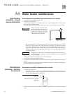
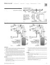
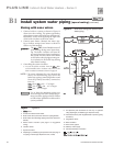
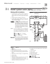
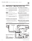
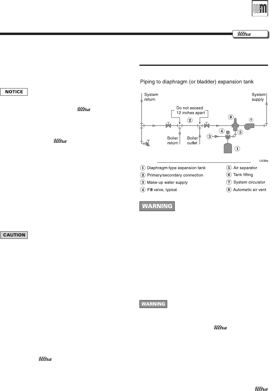
Figure 11 Expansion tank piping
B1
Gas
System water piping
methods
All piping methods shown in this manual
use primary/secondary connection to the
boiler loop. These designs ensure proper
flow through the Gas boiler, for
the most efficient and reliable operation
of the boiler and the heating system. For
other piping methods, consult your local
Weil-McLain representative or refer to
separate Gas boiler piping guides.
Wall-mounted boilers — Piping can exit
bottom of boiler enclosure. See separate
wall-mounting instructions for details.
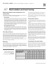
Expansion tank and make-up
water
1. Ensure expansion tank size will handle boiler and
system water volume and temperature. Allow 3
gallons for the boiler and its piping.
Undersized expansion tanks cause system
water to be lost from relief valve and
make-up water to be added through fill
valve. Eventual boiler failure can result
due to excessive make-up water addi-
tion.
2. Tank must be located as shown in this supplement,
or following recognized design methods. See tank
manufacturer’s instructions for details.
3. Connect the expansion tank to the air separator
only if the separator is on the suction side of the
system circulator. Always install the system fill con
-
nection at the same point as the expansion tank
connection to the system.
4. The piping drawings in this manual show only
diaphragm expansion tanks. Use only bladder-type
or diaphragm-type tanks with PLUS indirect water
heater applications.
5. Refer to the
Boiler Manual for other system
piping examples.
Diaphragm (or bladder) expansion tank
1. Always install an automatic air vent on top of the air
separator to remove residual air from the system.
2. See Figure 11 for correct location of the expansion
tank.
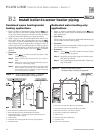
DO NOT USE a closed-type expansion tank
The boiler-side piping must be
equipped with a diaphragm- or
bladder-type expansion tank, NOT
a closed-type expansion tank. This
is necessary to allow venting air
from the top of the indirect water
heater boiler-side.
Boiler circulator
The boiler circulator is shipped loose. It must be located
in either the return or supply piping, as shown in the
appropriate piping diagram in this supplement or the
Boiler Manual.
DO NOT use the boiler circulator in any
location other than those shown in this
manual or the boiler manual. The boiler
circulator is selected to ensure adequate
flow through the boiler. Failure to
comply could result in unreliable per-
formance and nuisance shutdowns from
insufficient flow.
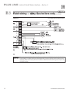
Sizing space heat system
piping
1. See Figures 12 and 13, pages 26 and 27, or the
Gas Boiler Manual for recommended piping. In all
diagrams, the space heating system is isolated from
the boiler loop by the primary/secondary connec-
tion.
2. Size the piping and components in the space heating