


8
Part Number PLUS-E017-A/1206
PLUS LINE
Indirect-Fired Water Heaters – Series 3
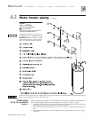
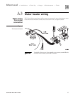
Temperature &
pressure (T & P)
relief valve
Air vent
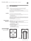
The boiler-side piping must be equipped with a diaphragm- or bladder-
type expansion tank, NOT a closed-type expansion tank.
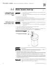
1. Remove plastic shipping cap from 1/2” NPT pipe fitting on top of water heater.
2. Install automatic air vent provided with water heater, using suitable pipe dope or tape.
3. Unscrew vent cap on air vent one full turn. Leave cap unscrewed one turn for normal
venting.
To reduce risk of excessive pressures and temperatures in water heater,
install temperature and pressure protective equipment required by local
codes, but no less than a combination temperature and pressure relief
valve certified by a nationally recognized testing laboratory that main-
tains periodic inspection of production of listed equipment or materials,
as meeting the requirements for Relief Valves and Automatic Gas Shutoff
Devices for Hot Water Supply Systems, ANSI Z21.22. This valve must be
marked with a maximum working pressure of the water heater.
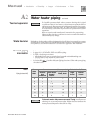
A2 Water heater piping
1. Size T&P relief valve by the following specifications, unless they conflict with local
codes:
• GOLD Plus 30/40/60/80 or
Plus 40/60/80: 3/4” NPT with an AGA Rating of
100,000 BTU/hr, with a long element. Set to relieve at 150 psi. (Watts model 100XL-8
relief valve or equivalent.)
• PLUS 100/110/119: 3/4” NPT with an AGA Rating of 200,000 BTU/hr, with a long
element. Set to relieve at 150 psi. (Watts model 40XL-8 relief valve or equivalent.)
GOLD Plus, Plus and PLUS water heaters are exempt from ASME Section VIII per
Interpretation VIII-1-86-136. Consult local codes for applicability.
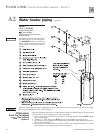
2. Installing T&P relief valve –
GOLD Plus 30/40/60/80 or Plus 40/60/80 (Page 9)
• Install T&P relief valve either:
a. in tapping marked AUX.
b. in run (straight through leg) of tee located at domestic hot water outlet of water
heater. (Required for the Commonwealth of Massachusetts.) Use a long element
T&P relief valve.
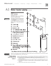
PLUS 100/110/119 (Page 11)
• Install T&P relief valve either:
a. in tapping marked
AUX.
b. in run (straight through leg) of tee located at domestic hot water outlet of water
heater. (Required for the Commonwealth of Massachusetts.) Use a long element
T&P relief valve.
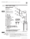
3. T&P relief valve discharge piping must be:
• made of material serviceable for temperatures of 250°F or greater.
• directed so that hot water flows away from all persons.
• directed to a suitable place for disposal.
• installed so as to allow complete draining of the T&P relief valve and discharge line.
T&P relief valve discharge piping must not be:
• excessively long. Using more than 2 elbows or 15 feet of piping can reduce discharge
capacity.
• directly connected to a drain. Terminate discharge piping within 6” from floor. Refer
to local codes.
• plugged, reduced or restricted.
Do not install any valve between T&P relief valve and tank connection,
or on T&P relief valve discharge piping. Do not plug T&P relief valve or
discharge piping. Improper placement and piping of T&P relief valve can
cause severe personal injury, death or substantial property damage.