


Part Number PLUS-E017-A/1206
59
Manual • Installation • Start-Up • Usage • Maintenance • Parts
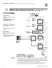
1. These drawings are conceptual only. They show representative piping components and
layout. Weil-McLain does not represent that the drawings meet any particular mechanical
or building codes. The installer is responsible for inclusion of all required safety devices, or
other miscellaneous piping hardware not shown on drawings. The installer is responsible
for proper sizing/selection of all hardware shown on this diagram.
2. Follow component manufacturer’s instructions for installation of all items shown.
3. See Weil-McLain installation instructions for specific details on installing the boiler.
Notes
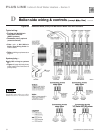
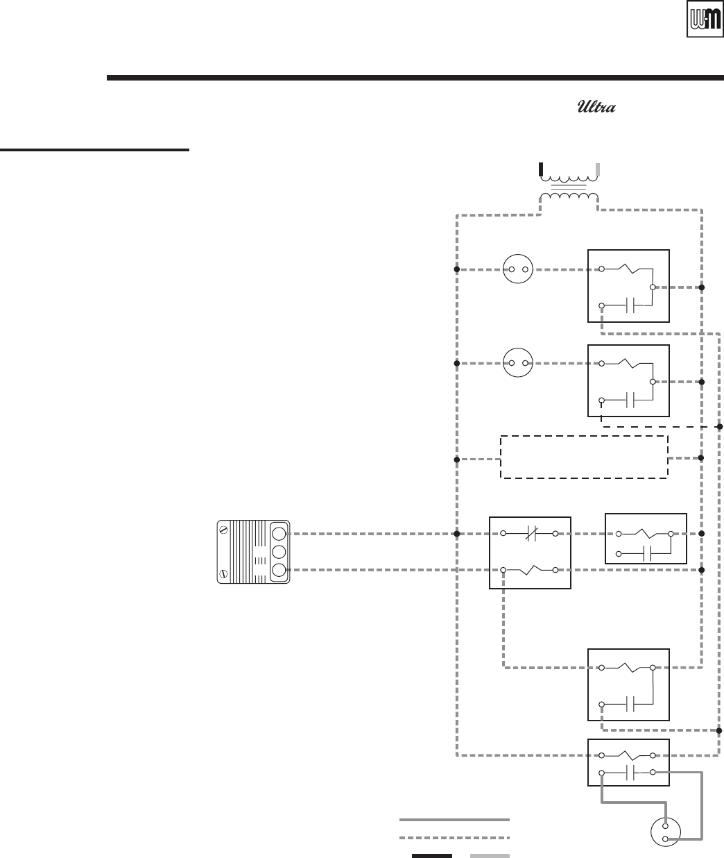
Figure 41
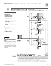
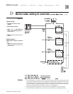
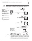
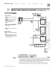
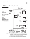
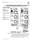
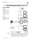
Typical wiring:
• Zoning with 3-wire zone
valves
• With domestic priority using
2-way priority valve
• Also refer to Weil-McLain
Boiler Zone Wiring Guide for
further details.
• Refer to Wiring requirements on
page 47.
System piping —
Apply this wiring to systems
in:
• Figure 23, page 39 (using 2-way
water heater zone valve and 2-
way priority valve)
✱
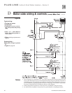
Room
thermostat
Transformer
(Power)
Zone valve
Room
Thermostat
Water heater
zone valve
Additional zones may
be added as shown above
Boiler
thermostat
terminals
Isolation
relay
Water heater
zone
24
V.A.C.
Zone 2
Zone
valve
Zone 1
Additional
zones
120
V.A.C.
High voltage
H N
*
Use Isolation Relay on
3-wire zone valves with
non-isolated end switches.
Transformer and boiler
control can burn out if
Isolation Relay is not used.
Water heater
thermostat
Snap Set
1
2
C
Low voltage (24 vac) field wiring
Low voltage boiler field wiring
NO
NC
High voltage (120 vac) field wiring
H N
500075-30b
Priority valve
Priority relay
Contact not
used
D Boiler-side wiring & controls (except Gas) continued