


22
Part Number PLUS-E017-A/1206
PLUS LINE
Indirect-Fired Water Heaters – Series 3
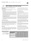
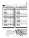
Table 2
Time lag to obtain hot water at
fixture for branch lengths of 10
and 25 feet
(ASPE Domestic Water Heating Design Manual)
Time in seconds required to get hot water at fixture (from ASPE)
Fixture flow rate (GPM) - 0.5 1.5 2.5 4.0
Piping length (feet) - 10 25 10 25 10 25 10 25
Copper pipe ½" 25 63 8 21 5 13 3 8
¾" 48 119 16 40 10 24 6 15
Steel pipe ½" 63 157 21 52 13 31 8 20
¾" 91 228 30 76 18 46 11 28
CPVC pipe ½" 64 159 21 53 13 62 8 20
¾" 95 238 32 79 19 48 12 30
NOTE: Select branch size and length for less than 31 seconds delay.
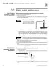
Maintaining domestic water temperature in the
supply piping
Two options are available to maintain supply temperature available at or
near the fixtures on storage water heating systems:
· Recirculation
Recirculation is used to reduce wait time for water use, to minimize
hot water and energy waste caused during the waiting period, and to
prevent degradation of the system supply water temperature. ASPE
recommends recirculation when the distance from the water heater
to the furthest fixture exceeds 100 feet or the time lag for hot water to
reach a fixture(s) exceeds 30 seconds. Consult local codes and American
Society of Plumbing Engineers (ASPE) Domestic Water Heating Design
Manual, 1998, for further information.
· Self-regulating heat tracing
Self-regulating heat tracing may be a better alternative than recircula
-
tion for residential and small commercial applications. Self-regulating
heat tracing uses electrical energy to maintain water temperature, but
it eliminates the need for return piping and components required in a
recirculation system.
Time delay at fixtures
Table 2 is from the ASPE Domestic Water Heating Design Manual, 1998. It
shows the time required for usable hot water to arrive at a fixture based on
the fixture flow rate (available from industry and manufacturer’s data) and
the length and diameter of the dead-end branch pipe supplying the fixture.
The time lag should generally not exceed 30 seconds. For residential and
office applications, the owner may prefer a limit of 10 seconds.
You can use Table 2 as a guide to determining the location of circula
-
tion return lines relative to fixtures.
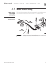
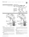
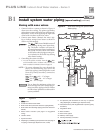
Balancing
When multiple branches are connected to the supply piping, each branch
must be connected to the recirculation system. At each of these connec
-
tions to the return piping, install shutoff valves, a flow metering device,
check valve and a strainer as shown in Figure 9 on page 23. Check local
codes for specific installation requirements.
These branches must be balanced to prevent pipe ero
-
sion and unacceptable time delays at some fixtures.
Balancing options include circuit setters, memory stop
valves or factory preset devices (with flow metering
provision in the piping).
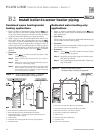
Components required
For residential applications, consult pump manufactur-
er’s data for pump selection and additional components
required.
On most commercial systems, install the devices shown
in Figure 9, page 23, and any other devices or piping
methods required by local codes. The check valves
are required to prevent fixtures from taking hot water
through the return lines. Shutoff valves are needed to
allow cleaning and replacing balancing devices. Include
strainers to remove sediment which could damage the
pump and/or affect the flow balancing devices.
Size the pump and piping based on the temperature
drop allowed between the water available at the water
heater and the water delivered at the fixture. The return
piping will almost always be smaller than the supply
piping, but should never be smaller than ½” to prevent
problems with the pump.
Make provision for removal of air in all return lines.
Where the returns cannot be vented by topmost fixtures
in the system, install automatic air venting at the top
of the return piping.
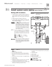
Connecting to the water heater
Install a recirculation dip tube in the AUX tapping on
top of the water heater. This requires mounting the
T&P relief valve as shown for Option 2 in the piping
diagrams, pages 10 and 12. See Figure 10, page 23, for
the piping required to the water heater.
Recirculation and heat tracingA7