


12
Part Number PLUS-E017-A/1206
PLUS LINE
Indirect-Fired Water Heaters – Series 3
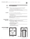
Figure 5
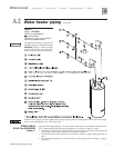
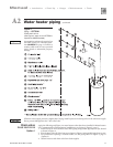
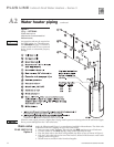
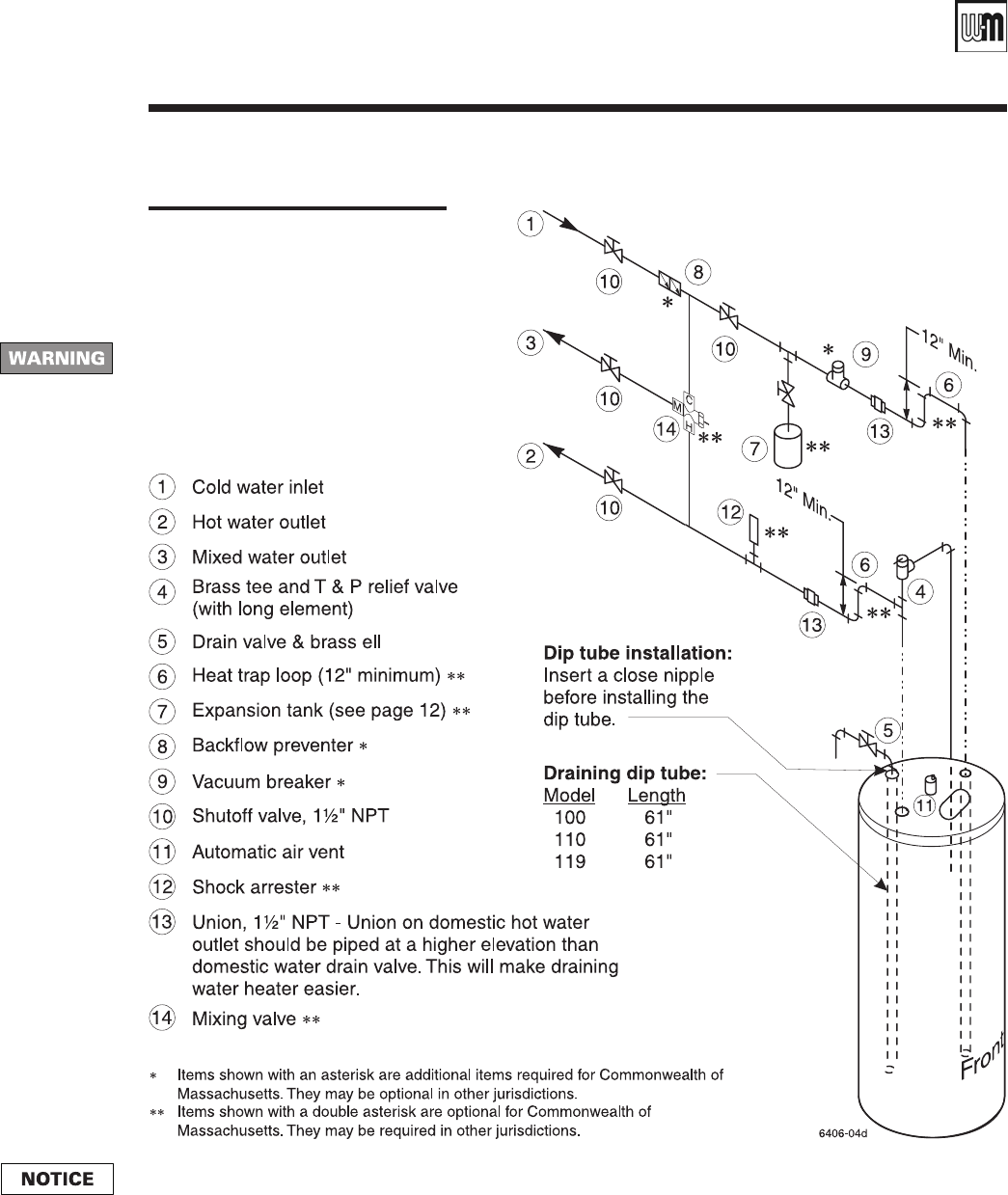
Piping — OPTION 2
PLUS 100/110/119
(Required for Commonwealth of
Massachusetts)
Drain valve
PLUS 100/110/119
Option 2
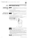
Apply the following and Figure 5 to water heaters installed in Massachusetts. The drain valve
is mounted in the AUX tapping on top of the water heater.
1. Insert an open-ended “draining” dip tube into the AUX tapping on top of the heater.
2. Connect a elbow to the AUX tapping, using suitable pipe dope or tape.
3. Pipe the drain valve to the elbow, using suitable pipe dope or tape, as shown in Figure 5.
4. Pipe the T & P relief valve in the run of the brass tee, located in the domestic water outlet
piping as shown in Figure 5.
5. Obtain brass tee and drain valve from local supplier.
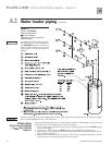
Water heater piping continuedA2
An expansion tank may be required on
the DHW piping. See Thermal expan-
sion WARNING on page 13. Failure to
comply could result in severe personal
injury, death or substantial property
damage.
When the water supply pressure is higher than 70 psig, install a pressure-reducing valve on the cold water supply
line to prevent leakage from the T & P relief valve.