


9
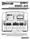
BMC and BMC-6X Installation and Operation Manual
WIRING
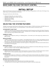
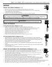
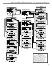
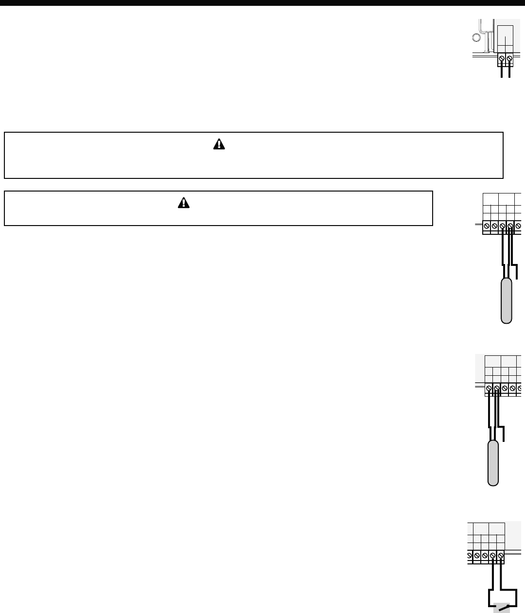
WIRING THE POWER (TERMINALS 1, 2)
• Bring the 120VAC 60Hz power wires through the bottom Knockout of the enclosure.
• Class 1 voltages must enter the enclosure through a different opening from any Class 2 voltage wiring.
• Connect the hot line to terminal marked L.
• Connect the neutral line to the terminal marked N.
• Weil McLain recommends installing a surge suppressor on the power source to the BMC.
WARNING
Class 1 voltages must enter the enclosure through a different opening from any Class 2 voltage wiring.
Weil McLain recommends installing a surge suppressor on the power source to the BMC.
1
2
L
N
PWR
Line
Neutral
120VAC
Power Sourc
e
WARNING
Connect the shield at the control terminal end and cut the shield wire at the sensor end.
29
25
27
26
28
T
T
O
O
TEMP
OUTDOOR
TEMP
SYSTEM
System Sensor
Sensor Shiled
PR
O
/DH
W
2
9
25
27
26
28
T
T
O
O
TEMP
OUTDOOR
TEMP
SYSTEM
Outdoor Sensor
Sensor Shiled
t
P
R
/D
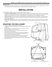
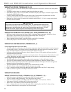
WIRING THE SENSORS
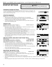
SYSTEM SENSOR WIRING (TERMINALS 27, 28)
• A BMC must be connected to a temperature sensor located in the common header.
• The BMC is designed to be connected to a 389-900-230 temperature sensor for immersion in a 3/8ID
well (592-300-023 or equivalent). Contact the factory for additional temperature sensor options.
• Temperature sensor wires can be extended up to 500’ by splicing shielded
2-conductor cable (Belden #8760 or equivalent (#18/2)).
• Temperature sensors have no polarity. Connect the two wires from the
sensor to the BMC terminals marked SYSTEM TEMP 27, 28.
• Connect the sensor shield to the circled terminal 28 with one of the sensor wires.
OUTDOOR SENSOR WIRING (TERMINALS 25, 26)
• When Outdoor Reset is selected, the BMC will vary the system Set Point based on outdoor temperature.
• Whether in Set Point or Outdoor Reset modes, the outdoor sensor can be used as an Outdoor Cutoff. The BMC
will disable all boilers when the outdoor temperature is above the adjustable Outdoor Cutoff temperature. This
feature will automatically be activated when an outdoor sensor is connected.
• For an outdoor sensor use a Weil McLain outdoor sensor (389-900-229).
• The sensor wires can be extended up to 500’ using shielded 2-conductor cable (Belden #8760 or equivalent
(#18/2)).
• Temperature sensors have no polarity. Connect the wires from the outdoor sensor to the BMC terminals marked
OUTDOOR TEMP - 25, 26.
• Connect the shield to the circled terminal 26 with one of the sensor wires.
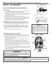
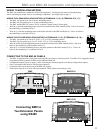
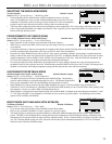
WIRING THE SHUTDOWN, TSTAT, OR SETBACK (TERMINALS 31, 32)
• The Shutdown will be available when selected as the Shutdown/Tstat/Setback mode from the Startup menu. See
page 15. This will provide the user with a customizable Day/Night Schedule. See page 21.
• The Shutdown feature can be used whenever it is desirable to turn off the BMC stage outputs from a remote
location or another controller (i.e. EMS input).
• The Tstat option, when selected from the Shutdown/Tstat/Setback startup menu, provide the capability of
controlling the operation of the BMC based on a thermostat input.
• The thermostat will provide the BMC with a call for heat by shorting terminals 31 and 32.
• When the Shutdown input is enabled by closing the dry contact, or when the Tstat input is disabled by opening
the dry-contact, all active boilers will immediately modulate down to low for the Soft-Off period, then turn off.
• The System Output relay will remain active until the System Delay is over and then it will turn off.
29
2
8
32
30
31
O
O
O
P
E
M
Shutdown,
T-Stat, or
Setback Signal
PROVE
/DHW
SHUTDOWN
/SETBACK
• When Setback is selected in the Startup, a BMS/EMS or external clock can provide a Setback signal using these input terminals.
• The signal must be a dry contact only. No voltage can be placed across the SHUTDOWN/TSTAT/SETBACK terminals.
• Bring the two wires from the dry contact to the terminals marked SHUTDOWN/TSTAT/SETBACK- 31,32.