


7
BMC and BMC-6X Installation and Operation Manual
System Run-On
• This feature lets the BMC run the SYS relay for a longer period after the boilers have been turned off. When this relay is used to
control a pump, it helps in dissipating the excess heat from the boilers combustion chamber.
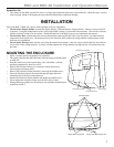
INSTALLATION
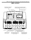
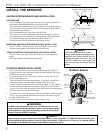
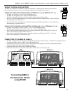
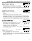
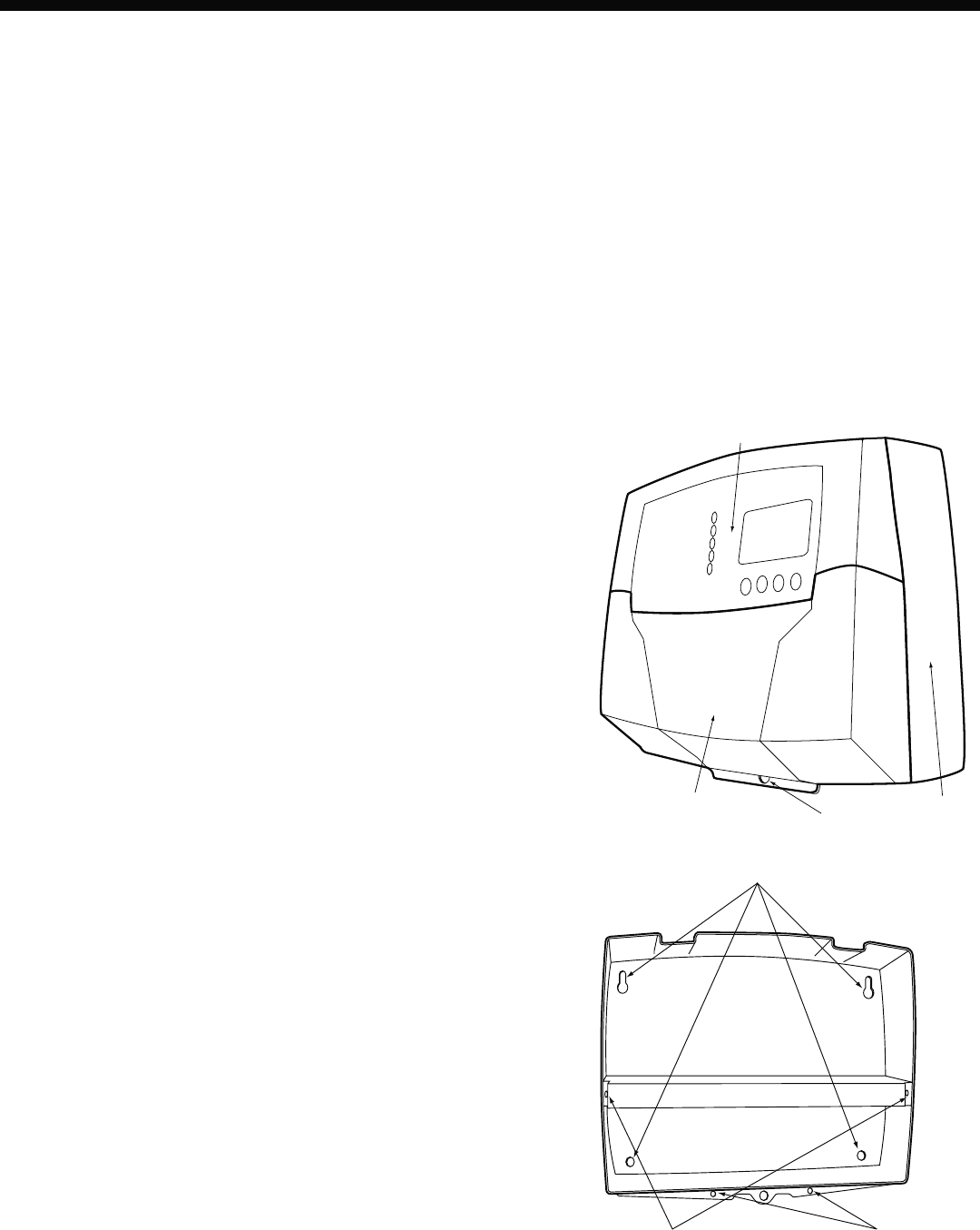
Each of the BMC or BMC-6X consists of three primary enclosure components.
• The Enclosure Display Module: contains the display, buttons, LEDs and electric wiring terminals. It has two screws to hold it
to the base. A program configuration switch, used to adjust BMC settings, is placed above the terminals. This switch is enclosed
with the enclosure wiring cover for security. Wiring terminals are of the plug-in type to ease installation and removal.
• The Enclosure Base: contains the holes to mount and hold the control against the wall or any flat surface. All other enclosure
components mount on the base. The bottom section of the Enclosure Base contains the wiring chamber with knockouts on the
bottom to easy installation.
• The Enclosure Wiring Cover: seals the wires from the external environment. It has two screws to hold it the base and a hole to
secure a lock on the wiring enclosure. A plastic web that separates the wiring chamber into high and low volt sections has been
provided.
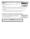
MOUNTING THE ENCLOSURE
• Select a location near the equipment to be controlled.
• The surface should be flat and sufficiently wide and strong to hold the BMC
or BMC-6X.
• Keep the control away from extreme heat, cold, or humidity. Ambient
operating temperature is from 20 to 120°F.
• Remove the Enclosure Wiring Cover from the control enclosure by
removing the two bottom screws.
• Remove the Enclosure Display Module by removing the middle screws.
• Screw the Enclosure Base to the surface through the upper and lower
mounting holes on the back of the enclosure.
• Replace the Enclosure Display Module and replace the middle screws.
• Do not replace the enclosure wiring cover until all wiring is done.
• When purchasing a padlock for the enclosure, the maximum shank diameter
should not exceed ¼"
Mounting Base
Display Mounting Screws Wiring Cover Mounting Screws
Enclosure Display Module
Enclosure Wiring Cover Enclosure Base
Hole for optional lock