


3
BMC and BMC-6X Installation and Operation Manual
BMC
SYSTEM
A
B
C
D
Full Modulation Sequencing Control
1
2
RUNPROGRAM
FOR ALL CIRCUITS
120VAC, 6A RESISTIVE
OUTPUT RATINGS:
1A PILOT DUTY, 15A TOTAL
115VAC 60Hz , 30VA MAX
INPUT RATINGS:
USE COPPER WIRE,
DO NOT APPLY ANY VOLTAGE
TO INPUT TERMINALS
3
4
5
6
7
8
9
10
11
12
13
15
14
17
16
18
22
20
19
21
24
23
29
25
27
26
28
32
30
31
L
N
-
+
+
T
T
O
O
RS-485
mA
GND
VLT
SYS
A
B
C
D
PWR
CUR / VLT
A
-
+
+
mA
GND
VLT
-
+
+
mA
GND
VLT
-
+
+
mA
GND
VLT
+
mA
TEMP
OUTDOOR
O
O
TEMP
SYSTEM
EXTENSION
MODULE
CUR / VLT
B
CUR / VLT
C
CUR / VLT
D
CLASS 1 WIRE ONLY.
------
SYSTEM
PROVE
SHUTDO
W
N
/TSTAT
/SETBACK
ENCLOSED
ENERGY
MANAGEMENT
EQUIPMENT
LISTED
99RA
CAUTION: RISK OF ELECTRIC SHOCK
More than one disconnect switch may be required
to de-energize the equipment before servicing.
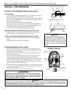
CUS
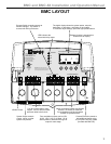
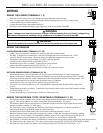
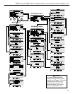
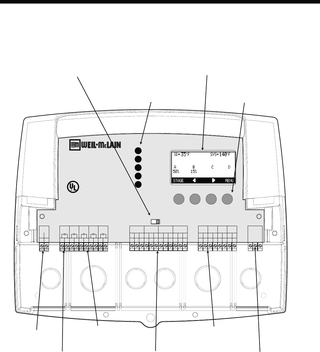
The digital display shows the system status, set point,
lead stage <in brackets>, and status of each stage.
To view and adjust settings, press the appropriate buttons.
120VAC Power
Four N.O. Boiler startup relay
outputs. Each is wired in series
with each boiler's limit circuit.
System Output controls
pumps, valves, or other
system components.
Four modulation outputs can be 0-5V,
0-10V, 1-5V, 2-10V, or 4-20ma. Go to
Startup Menu to determine the type of
output for each stage.
LED indicates the
associated relay status.
Buttons function is presented on
Bottom Row of display.
When connecting Outdoor and System
Sensors, no Polarity is observed.
Prove terminals must be connected
for BMC to operate boilers.
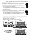
Connect Extension panels to
add additional stages using
a 6 pin phone line only (cable
provided with BMC-6X).
Program Switch to restrict access to
function changes. This switch is
covered with Wiring Enclosure.
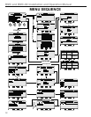
BMC LAYOUT