


25
BMC and BMC-6X Installation and Operation Manual
DISPLAY MESSAGES
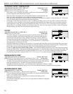
The BMC normal display layout reserved the second line for message indications. The following is a list of the most common
Message Display Line information:
• Summer The control is set to Summer. No heat is active. See Season on page 17.
• Shutdown Active The Shutdown Terminals are Shorted. No boilers will be active. See Shutdown on pages 15 and 9.
• Shutdown by EMS The EMS is below 2mA or above 22mA. See EMS input and External Set Point pages 14 and 31.
• Tstat Call The Tstat Terminals are Shorted. Boilers will be active.
• DHW Call (171˚F) There is a DHW (Domestic Hot Water) call. The BMC will Raise system Set Point to the indicated
temperature. DHW increases calculated temperature to 200˚F or Max Water Temperature, whichever
is lower. See DHW setting on page 15.
• Purge Delay: 23 The current boiler is in purge cycle and the remaining purge time in seconds is 23. See Purge Delay
on page 19.
• Lag Delay: 123 The lead boiler is at 100% and the remaining purge time to start the lag boiler in seconds is 123. See
Lag Delay on page 20.
• Holding Until 150˚F The Lead boiler is in Last Stage Hold. This example shows that the lead stage will turn off when
system temperature reaches 150˚F. See Last Stage Hold on page 21.
• System Run-On: 46 The System relay is ON for the System Run-On Delay. This example shows that it will remain in
System Run-On for an additional 46 seconds before turning off. See System Run-On on page 20.
• Waiting for Prove The System relay is ON and the prove terminals are open before the lead boiler relay can energize.
See Prove setting on page 15.
• Prove Failure After boilers have run for a while, Prove signal was opened. The boiler relays will de-energize.
However, the System relay will remain energized. See Prove setting on page 15.
BOILER STAGE SETTINGS
Button: STAGE/
The Maintenance menu gives access to sensor and outputs trimming and Soft-Off. In
addition, you'll have access to view the Startup configuration settings.
• In most installations, all active boiler adjustments are the same, but each can be
configured differently if desired.
• If the boilers are not set up properly, the BMC operation may appear to be erratic.
• When the STAGE button is depressed, the Boiler A Settings menu will be shown.
• Make all the appropriate settings for Boiler A (See below).
• After completing all the settings for Boiler A (See below), you have the option of
copying these settings to all other boilers. Everything but the Mode -- Auto/Standby/
Manual/Off/On -- will be copied.
• Then select the Next Stage option from the menu to bring up the Boiler B Settings menu
and make all the settings. Continue until all boilers have been set.
• If a BMC-6X is connected to the BMC, scrolling through stages using the Next and Prev
Stage menu options will scroll through the BMC-6X stages as well.
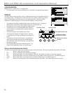
ALERT
To be able to change the BMC settings, the Program/Run Switch must be set to
Program. The switch is located under the Enclosure Wiring Cover for security.
The Enclosure Wiring Cover can be securely closed using a lock.
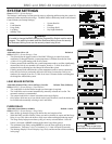
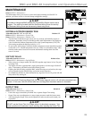
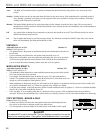
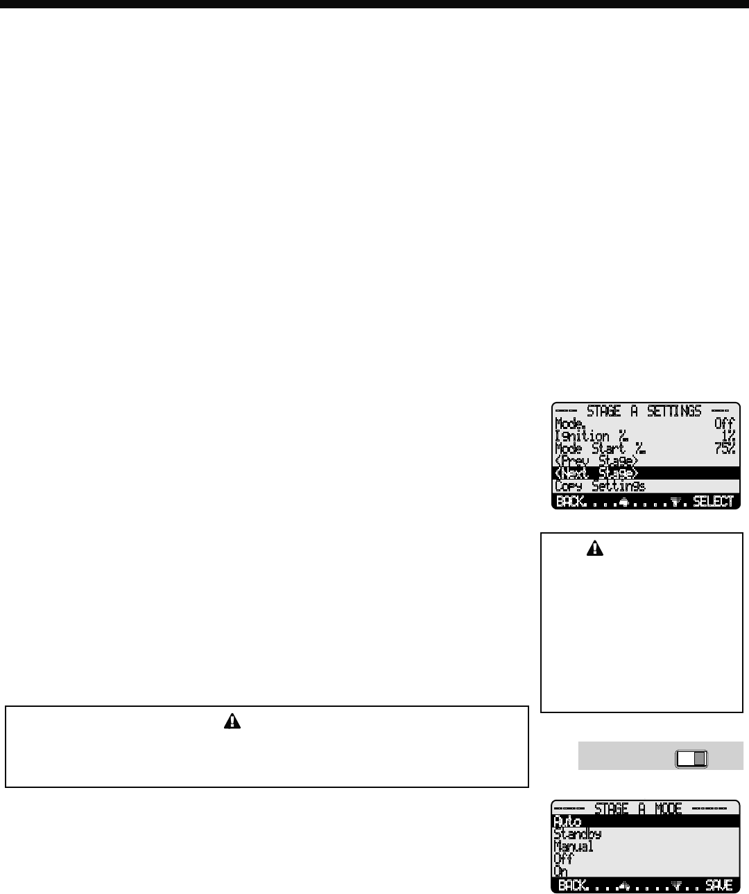
----- STAGE A SETTINGS ----
Mode Off
Ignition % 1%
Mode Start % 75%
<Prev Stage>
<Next Stage>
Copy Settings
BACK SELECT
CAUTION
Remember to set the Mode
for each stage. For Stages
that do not have a boiler,
contractor must change their
Mode to OFF. Otherwise the
BMC will include them in the
modulation calculation and
rotation. That might have dire
effects on system response.
RUNPROGRAM
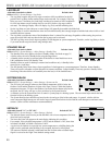
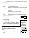
MODE
Auto, Standby, Manual, Off, On Default: Auto
Button: STAGE/Mode
• The BMC only controls the modulation of boilers set to Auto or (after a delay) those set
to Standby. None of the other settings is recommended for output boilers connected to
active units.
• Any boiler without an active unit connected must be set to Off.
• The following list describes the MODE options:
BACK SAVE
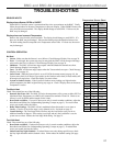
------- STAGE A MODE --------
Auto
Standby
Manual
Off
On