


10
BMC and BMC-6X Installation and Operation Manual
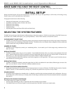
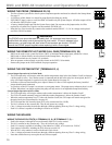
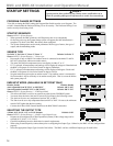
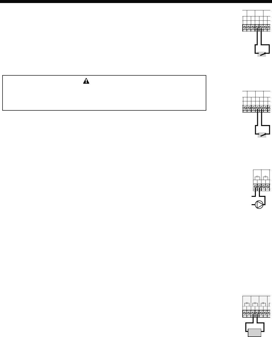
WIRING THE PROVE (TERMINALS 29, 30)
• The Prove feature is provided to check system component operation and must be selected in the Startup Menu.
See page 15.
• A typical use of this feature is to check for pump flow before firing any boiler.
• If the PROVE input is open on a call, the BMC will enable only the System Output. All boiler outputs will be
off when the PROVE input is open.
• A factory-installed jumper provides the System Prove signal. Do not remove the jumper unless it will be
replaced by a System Prove signal or use the terminals for DHW call.
• Bring the two wires from the dry contact to the terminals marked PROVE - 29, 30. No voltage can be placed
across the PROVE terminals
WARNING
The PROVE input cannot be used as a safety limit. All equipment must have its own
certified limit and safety controls as required by local codes. If Prove is selected in the
startup menu, no boiler stage will start unless Prove terminals are shorted. DO NOT
remove the PROVE jumper supplied unless replacing it with a Prove signal.
29
27
26
28
3
2
30
31
T
O
O
E
MP
D
OOR
O
O
TEMP
SYSTEM
Prove Signal
PROVE
/DHW
SHUTDO
W
/SETBAC
K
29
5
27
26
28
3
2
30
31
T
O
O
E
MP
DOOR
O
O
TEMP
SYSTEM
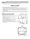
DHW Signal
PROVE
/DHW
SHUTDO
W
/SETBAC
K
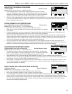
WIRING THE DOMESTIC HOT WATER CALL DHW (TERMINALS 29, 30)
• DHW can be used to raise system Set Point to 200°F or Maximum Water temperature, whichever is lower.
DHW with or without Priority must be selected in the Startup Menu. See page 15.
• DHW Call terminals are dry contact N.O. terminals.
• Wire an aquastat or other controls to provide closure on the DHW Call terminals.
• Remove the jumper on the DHW terminals for proper operation.
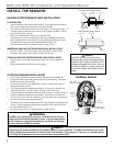
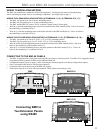
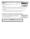
WIRING THE SYSTEM OUTPUT (TERMINALS 3, 4)
System Output Operation in Set Point Mode
• The SYS output relay will energize when the outdoor temperature drops below the Outdoor Cutoff or whenever
a boiler output is active. If no outdoor sensor is connected and the last boiler relay has de-energized, the SYS
relay will remain energized for a period set by the System Run-On. See page 20.
• No boilers will be activated until the prove input is shorted. If a Prove is not required, the factory-installed
jumper should remain connected.
• A typical use of the SYS output is to activate a system pump starter. The pump can run whenever there is a call
for heat. When heat is no longer required, the pump will stay active for an adjustable Pump Run-On delay.
3
4
5
6
SYS
A
System Pump
or Pump Starter
L
N
System Output Operation in Reset Mode
• The SYS output relay will energize whenever the outdoor temperature is below the Outdoor Cutoff.
• The SYS will remain constantly energized while the outdoor temperature is below the Outdoor Cutoff.
• When the outdoor temperature rises 2°F above the Outdoor Cutoff, the SYS output will remain energized for
the period set by the System Run-On. See page 20.
• The SYS output has one Normally Open (N.O.) relay contact rated for (1/8HP).
• The N.O. contacts are dry contacts only. They do not source any voltage.
• Class 1 voltages must enter the enclosure through a different opening from any Class 2 voltage wiring.
• Each N.O. contact is capable of switching 6A resistive at 120VAC.
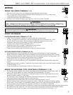
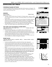
WIRING THE BOILERS
WIRING THE BOILER OUTPUTS (A TERMINALS 5, 6), (B TERMINALS 7, 8), ...
• Each boiler output (A through D) has one Normally Open (N.O.) relay contact.
• The N.O. contacts are dry contacts only. They do not source any voltage.
• Each N.O. contact is capable of switching 1Amp inductive (1/8HP), or 6A resistive at 120VAC.
• Total output of all boilers, including the SYS, must not exceed 15A.
• Wire the N.O. relay contacts in series with the unit’s limit circuit.
• Class 1 voltages must enter the enclosure through a different opening from any Class 2 voltage wiring.
• Note that some boilers may not require the use of these outputs.
5
6
7
8
9
10
1
1
A
B
C
Boiler Enable
Output
Boiler