


8
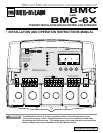
BMC and BMC-6X Installation and Operation Manual
INSTALL THE SENSORS
HEATING SYSTEM SENSOR (HSS) INSTALLATION
LOCATING HSS
• Put the Heating System sensor approximately 10' feet past the last boiler on
the common supply header but before any major takeoffs.
• The sensor must be located where it sees the output of all the boiler stages. If
a boiler is piped so that the sensor does not see its output, the BMC will not
sequence the boilers correctly.
• Only use a Standard Brass Tube sensor (389-900-230).
• The sensor wires can be extended up to 500' using a shielded 2-conductor
cable (Belden #8760 or equivalent). Do not ground the shield at the sensor
but at the panel using one of the terminals marked with an “O”.
• Do not run sensor wires in conduit with line voltage wiring.
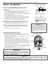
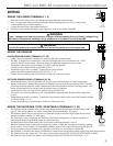
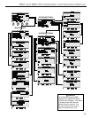
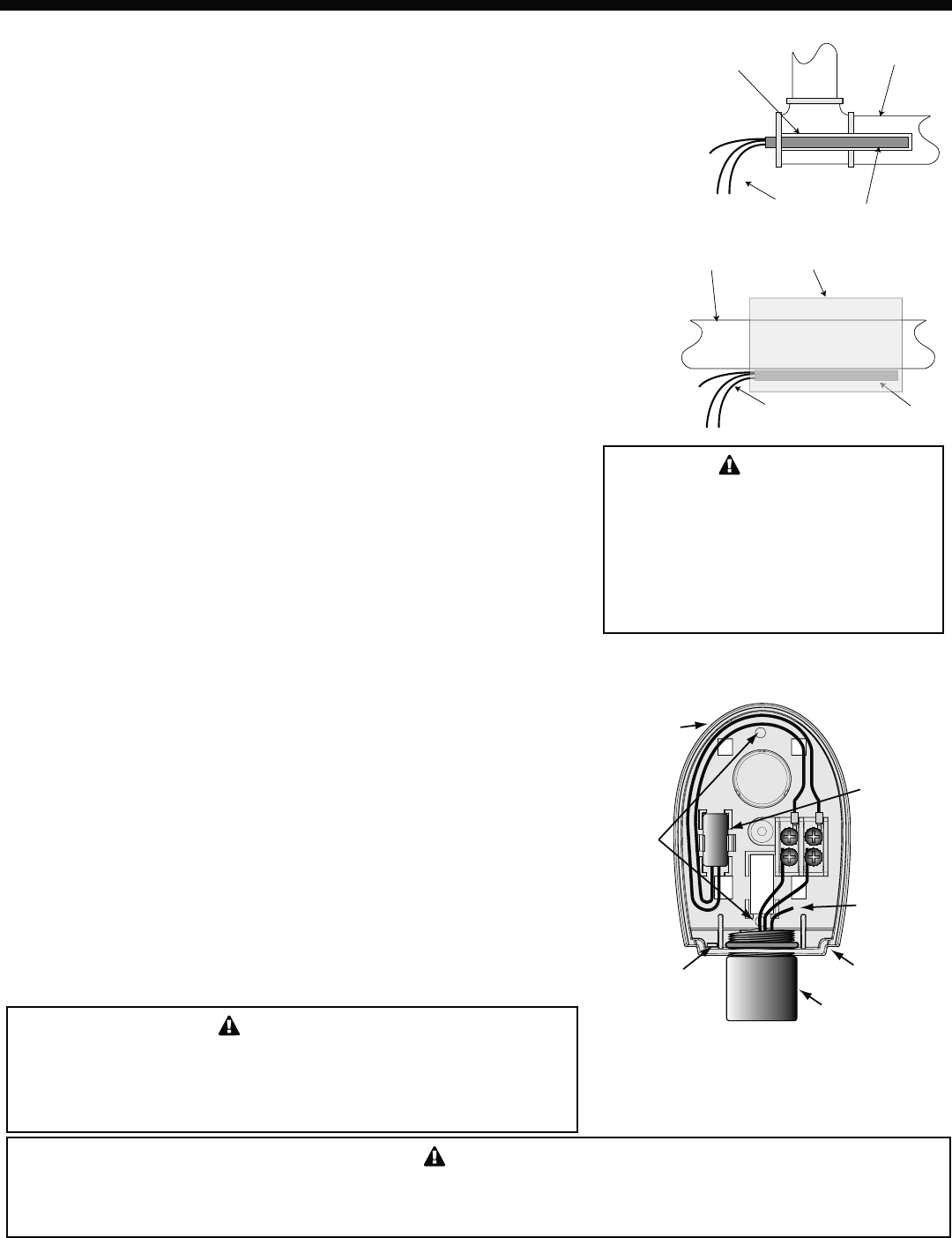
IMMERSION HEATING SYSTEM SENSOR (HSS) INSTALLATION
• Install a 3/8"ID 1/2"NPT immersion well (592-300-023 or equivalent).
• Insert the sensor probe of the supplied sensor into the well.
STRAP-ON HEATING SYSTEM SENSOR (HSS) INSTALLATION
• Strap the sensor to the pipe using metal clamps. Do not over tighten the
clamp.
• Strap pipe insulation around the sensor and pipe.
Immersion Well
3/8" ID 1/2" NPT
Heating System
Sensor
Common Supply Pipe
Sensor Probe
Immersion Heating System Sensor
Shield
Common Supply Pipe
Sensor Probe
Strap-On Heating System Sensor
Shield
Pipe Insulation
ALERT
If the HSS can not sense the correct
heating system water temperature being
supplied to the building, the BMC will not
provide comfortable heat levels. Be sure
the HSS is located on a main supply pipe
which can not easily be isolated from the
system.
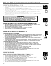
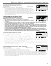
OUTDOOR SENSOR INSTALLATION
• Only use the Weil McLain sensor included with the unit (389-900-229).
• Locate the sensor in the shade on the north side of the building. The sensor
should never be in direct sunlight.
• Be sure the location is away from doors, windows, exhaust fans, vents, or
other possible heat sources.
• The sensor should be mounted approximately 10' feet above ground level.
• Adhere the Outdoor Label provided to the back of the sensor base.
• Use the Enclosure Base bottom knockout for the conduit. Use the locknut to
hold the conduit and enclosure base together. Screw the cover to the base.
• If screws are used to affix the enclosure to the wall, make sure to seal around
the sensor and wall except from the bottom.
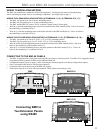
• The sensor wires can be extended up to 500' using shielded 2-conductor cable
(#18/2). Do not ground the shield at the sensor but at the control using the
terminal marked with an “O”.
• Do not run sensor wires in conduit with line voltage wiring.
WARNING
The BMC is an operating control only. All boilers must have all
safety and limit controls required by code. It is the responsibility
of the installer to verify that all the safety and limits are working
properly before the BMC is installed.
ALERT
Determining the proper location for the Outdoor Sensor is very important. The BMC will base the heat on the
outdoor temperature information it receives from this location. If the sensor is in the sun, or covered with ice,
its reading will be different from the actual Outdoor temperature (OD).
Outdoor
Sensor
snap-in
location
Shield
not connected
Conduit
Outdoor Label
on back of Sensor
Outdoor Sensor
Mounting
screws
location
Seal around
sensor and wall
Outdoor
drip-hole