


Weil-McLain 80 Boiler For Gas, Light Oil, Gas/Light Oil Fired Burners
32 Part No. 550-141-935/0602
Install burner14
Wiring and fuel piping
Make final adjustments16
15
To install burner:
1. Unpack burner.
2. Place gasket around air tube and against burner mounting flange.
If sealing rope is used, apply
1
/
8
" continuous bead of rope adhesive
around burner mounting flange and apply sealing rope to make
gas-tight seal.
3. Mount burner into opening in burner mounting plate.
Maintain gas-tight seal between burner mounting
flange and plate to prevent damage to air tube.
4. Level burner using burner support brackets where required.
5. Secure with furnished bolts.
6. Retain burner information packet. Keep with boiler.
Electric shock hazard. Can cause severe personal
injury or death if power source is not disconnected
before installing or servicing boiler and burner.
To wire burner and boiler controls:
1. Install all wiring in compliance with:
• National Electrical Code ANSI/NFPA 70.
• Any additional national, state, or local codes.
2. Follow burner manual and wiring diagram found in burner
information packet.
3. Use 14 ga. wire for operating and safety circuit wiring.
4. Where burner motor voltage differs from control voltage, supply
proper voltage to each. Size fused disconnect(s) and conductors
per National Electrical Code ANSI/NFPA 70.
To install gas and/or oil piping:
1. Install all piping in compliance with:
• Local, state or national codes and regulations.
• Seperate burner manual provided with burner.
2. Use pipe joint compound (pipe dope) resistant to corrosive action
of fuel oil or liquified petroleum gases. Apply sparingly to male
threads of pipe joints. Do not use any kind of pipe tape.
3. Oil piping – use flare-type fittings, not compression type.
Do not use compression or soldered fittings. No safe
repair can be made. Severe personal injury, death
or substantial property damage will result.
Propane boilers — see WARNING on page 39
regarding propane gas odorant.
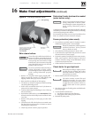
Adjust burner and damper assembly:
1. Lock open flue transition damper.
Make final burner adjustments using combustion test equipment to
assure proper operation. Do not fire boiler without water. Sections will
overheat, damaging boiler and resulting in severe property damage.
2. Refer to burner manual for start-up and service.
3. Let burner advance to high fire. Heat boiler to design conditions.
4. Using combustion test equipment, adjust burner for:
a. 12% (± ¼%) CO
2
for No. 2 fuel oil, 0 smoke.
b. 9 – 10% CO
2
natural gas; CO in flue gas not to exceed 50 ppm (0.01%).
5. Adjust damper assembly (Figure 35, page 33) to ensure 0.1" W.C. positive pressure
at test opening. Tighten screws to secure in position. Plug test opening with 3/8"
bolt provided with damper assembly.
6. Adjust barometric draft control, when used, to design conditions.
7. Repeat steps 4 through 6. Adjust as required.
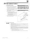
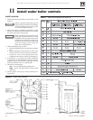
To fill water boilers:
1. Close manual air vents and drain cocks.
2. Fill to correct system pressure. Correct
pressure will vary with each installation.
3. Starting on lowest floor, open air vents one
at a time until water squirts out. Close vent.
Repeat with remaining vents.
4. Refill boiler to correct pressure.
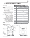
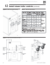
To fill steam boilers:
1. Do not fill (except for leakage test) until
boiler is ready to be fired.
2. Fill to normal waterline, halfway up gauge
glass.
3. Recommend boiler water pH 7.0 to 8.5.