


Weil-McLain 80 Boiler For Gas, Light Oil, Gas/Light Oil Fired Burners
12 Part No. 550-141-935/0602
Install flue collector (continued)6
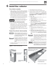
Before installing flue collector
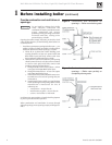
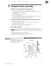
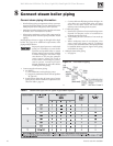
1. See Figure 10, page 11, for general assembly of flue
collector components.
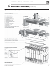
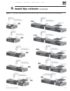
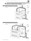
2. See Figure 11, page 13 for the placement of flue collector
hoods on each model.
3. Prepare mounting holes in boiler rear section.
a. The boiler rear section has tapped holes for mounting
rear flue collector component.
b. Remove any grit from threads inside tapped holes with
clean rag.
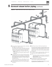
Rear flue boilers only:
1. See Figure 10, page 11 and Figure 11, page 13.
2. Place collector hood transition on rear section:
a. Wipe item 10, Figure 10, collector hood transition
flange surfaces with a clean rag.
b. Apply a few pieces of double-faced tape on the
collector hood transition flange.
c. Place the
collector hood transition gasket (item 8,
Figure 10) on the collector hood transition flange.
Align holes in gasket with holes in flange. Press gasket
firmly in place.
d. Position collector hood transition on back of boiler
rear section, aligning collector hood transition flange
holes with tapped holes in boiler rear section.
e. Insert a 5/16" x 5/8" flanged bolt through the bottom
center hole and finger tighten to hold transition in
place.
f. Install six remaining bolts securing collector hood
transition to rear section.
Finger-tighten only.
3. Place collector hood assembly on sections:
a. Carefully set collector hood assembly on top of section
assembly. Align slotted holes in collector hood flanges
with the hold-down bolts in the sections.
b. Place the collector hood assembly so its rear flange is
against the collector hood transition flange gasket.
c. Thread flanged nuts onto hold-down bolts and
finger-
tighten only.
d. Insert five 5/16" x 5/8" flanged bolts through holes in
collector hood transition and collector hood assembly
rear flange. Thread on nuts and
finger-tighten only.
4. Tighten flue collector bolts and nuts:
a. Gradually tighten all bolts and nuts on flue collector
assembly and boiler.
Tighten to between 30 and 35
inch-pounds torque. See WARNING, upper right.
b. Alternate locations as you tighten the fasteners to
ensure all parts are evenly drawn down, with no gaps
or distortion of parts.
5. Install damper and flue caps:
a. Wipe item 5, Figure 10, flue damper flange surface
with a clean rag.
b. Apply a few pieces of double-faced tape to the flue
damper flange. Position flue collar gasket on damper
and press firmly in place. Align all holes before
securing.
c. Position flue damper assembly against collector hood
transition. Insert a #10 x ½" screw through the top
center hole. Lightly tighten to hold flue damper in
position.
d. Insert remaining #10 screws into flue damper flange
and lightly tighten. Alternate from screw to screw and
tighten all screws evenly and securely.
e. Install flue caps on flue collector top opening(s) using
steps 5a through 5d.
DO NOT overtighten bolts in flue collector hood assembly.
Gasket material could extrude, causing possible flue gas leakage
and carbon monoxide emissions, resulting in severe personal
injury or death.
Top flue boilers only:
1. See Figure 10, page 11 and Figure 11, page 13.
2. Place rear flue cap on rear section:
a. Wipe item 9, Figure 10, rear flue cap gasket surface with a clean rag.
b. Apply a few pieces of double-faced tape on the rear flue cap gasket surface.
c. Place the
rectangular gasket (item 8, Figure 10) on the flue cap, aligning
holes in gasket with holes in rear flue cap. Press firmly in place.
d. Position rear flue cap on back of boiler rear section, aligning rear flue cap
holes with tapped holes in boiler rear section.
e. Insert a 5/16" x 5/8" flanged bolt through the bottom center hole and finger
tighten to hold rear flue cap in place.
f. Install six remaining bolts securing rear flue cap to rear section.
Finger-
tighten only.
3. Place collector hood assembly on sections:
a. Carefully set collector hood assembly on top of section assembly. Align
slotted holes in collector hood flanges with the hold-down bolts in the
sections.
b. Place the collector hood assembly so its rear flange is against the rear flue
cap gasket.
b. Thread flanged nuts onto hold-down bolts and
finger-tighten only.
c. Insert five 5/16" x 5/8" flanged bolts through holes in rear flue cap and
collector hood assembly rear flange. Thread on nuts and finger-tighten only.
4. Tighten flue collector bolts and nuts:
a. Gradually tighten all bolts and nuts on flue collector assembly and boiler.
Tighten to between 30 and 35 inch-pounds torque. See WARNING, above.
b. Alternate locations as you tighten the fasteners to ensure all parts are evenly
drawn down, with no gaps or distortion of parts.
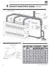
5. Install damper and flue caps (see Figure 11, page 13):
a. Wipe item 5, Figure 10, flue damper flange surface and flue collector
assembly surfaces with a clean rag.
b. Position round gasket (item 7, Figure 10) on flue collector assembly
in the
flue location shown in Figure 11, page 13
. Align bolt holes.
c. Place flue damper assembly on gasket. (See NOTICE, below.) Insert #10 x
½" screws through the holes. Alternate from screw to screw and tighten all
screws evenly and securely.
Model 380 top flue applications — always mount the damper
assembly with the damper adjustment plate pointed toward
the rear of the boiler as shown in Figure 11. Otherwise, the
jacket top panels may be difficult to install.
e. Install flue cap on remaining top opening (if any) using steps a through c,
above.
After installing flue collector, ALL BOILERS
1. Check for gas-tight seal of all flue collector hood components.
All collector hood joints must be sealed gas-tight to prevent
possible flue gas leakage and carbon monoxide emissions,
resulting in severe personal injury or death.
a. Open flue damper. Visually inspect inside section assembly and flue collector
assembly for any light passing through unsealed areas.
b. Mark all unsealed areas.
c. Check unsealed areas for cause — damaged gaskets, sealing rope not in
place, or loose bolts or nuts.
d. Correct all conditions and repeat inspection procedure.
e. If unsealed areas cannot be eliminated, discontinue the boiler installation.
Contact your Weil-McLain distributor or sales office for assistance.