


Weil-McLain 80 Boiler For Gas, Light Oil, Gas/Light Oil Fired Burners
14 Part No. 550-141-935/0602
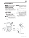
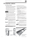
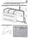
Connect water boiler piping7
General water piping information:
• System water supply and return piping should be installed and piping
connections attached to boiler before erecting jacket or installing controls.
• Do not pipe in through supply and out through return. This creates reverse
water flow through boiler that must not be used.
• When three-way valves are used for temperature modulation, install slow-
opening (minimum 10-minute) valves and boiler mixing pump to minimize
potential of boiler thermal shock. See W-M Bulletin AE-8402.
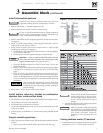
Install piping:
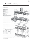
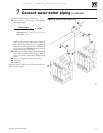
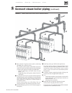
Install piping as shown in Figure 12 for single boilers. For multiple boilers, see
Figure 13, page 15.
Improperly piped systems or undersized piping can contribute
to erratic boiler operation and possible boiler or system
damage.
1. Connect supply and return piping:
a. Size according to tables below.
1) For
unknown flow rates, size piping per Table below, using 20°F.
temperature rise through boiler.
2) For
known flow rates or higher flow rate through boiler, size
piping per Table below.
Flow at higher rates than shown in Table below for pipe size
can damage boiler, causing substantial property damage.
b. Locate circulator in supply piping.
c. For return piping, use full diameter pipe for 10 times that diameter before
making any reduction. For example, a 4-inch return should not be
reduced any closer to boiler return tapping than 40 inches.
d. Install system blow-off (drain) valve in lowest part of return piping close
to boiler. ASME minimum size requirements are shown in Table 5.
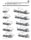
2. Install expansion tank:
a.
Closed type – connect to 1" tapping “K” (refer to pages 28 and 29).
Use 1” N.P.T. piping. Any horizontal piping must pitch up toward tank
at least 1 inch per each 5 feet of piping.
b.
Diaphragm type – Refer to tank manufacturer’s literature for location.
Install automatic air vent in “K” tapping.
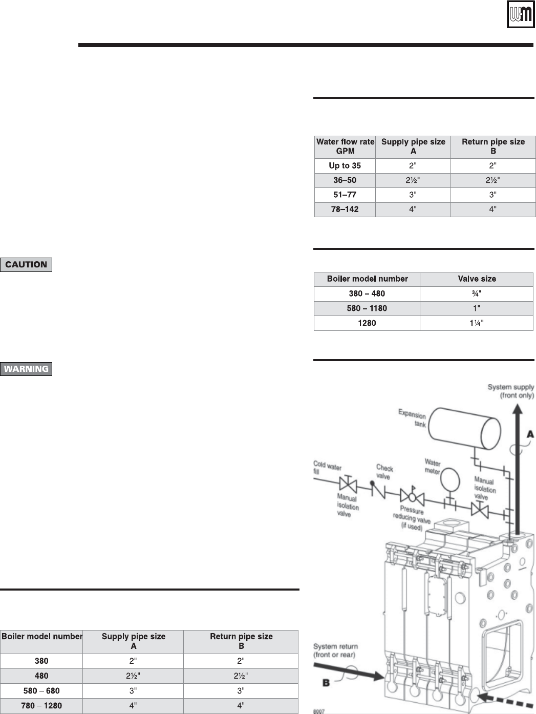
c. Connect cold water fill to expansion tank piping. See Figure 12, page 14.
Also shown are recommended valves and water meter, when used. Water
meter will detect added make-up water, indicating leaks in system.
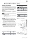
Table 7 ASME drain valve size
Table 6 Recommended minimum pipe sizes for
known flow rates.
Table 5 Recommended minimum pipe sizes when flow rate is
not known (see Figure 12)
Figure 12 Water boiler piping, typical