


Weil-McLain 80 Boiler For Gas, Light Oil, Gas/Light Oil Fired Burners
10 Part No. 550-141-935/0602
Install flue collector6
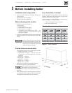
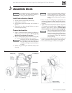
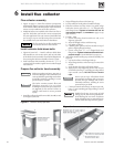
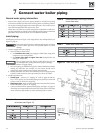
Figure 8 Collector hood preparation
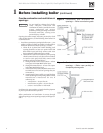
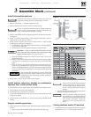
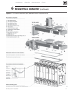
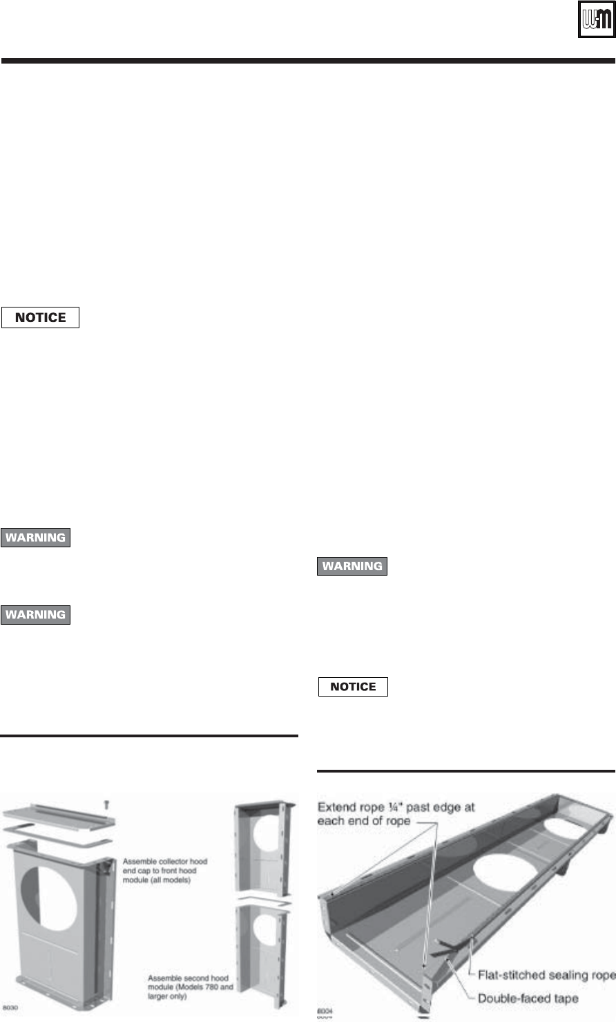
Figure 9 Flue collector sealing rope installation
Flue collector assembly
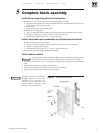
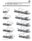
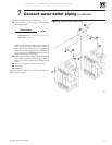
1. Figure 10, page 11, shows flue collector components
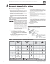
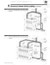
and locations. Figure 11, page 13, shows collector hoods
for all models. Follow all instructions in this manual to
ensure correct installation of the flue collector.
2. Model 80 boilers are available with either rear flue or
top flue. Verify that you have the correct components
for your application. You can convert a Model 80 from
rear to top or top to rear flue using a flue conversion
kit, available from your Weil-McLain distributor.
The flue outlet for top flue models must
be located as shown in this manual.
Install collector hold-down bolts
1. Figure 10, lower left — Install a collector hold-down
bolt assembly at each section joint, and on both sides
of the boiler section assembly. Set aside the flanged nuts
for securing the collector assembly when it is ready.
2. Each hold-down bolt assembly consists of a
5
/16" x 2"
carriage bolt, flat washer, regular hex nut and a flanged
nut as shown.
Prepare flue collector hood assembly
Make sure gaskets are intact, not torn or
otherwise damaged. These conditions can
cause possible flue gas leakage and carbon
monoxide emissions, resulting in severe
personal injury or death.
The boiler contains ceramic fiber and
fiberglass materials. Use care when
handling these materials per instructions
on page 38 of this manual. Failure to
comply could result in severe personal
injury.
1. Stand flue collector hood front module (item
4) on end
as in Figure 8, left side.
2. Wipe all flanged surfaces with clean rag.
3. Lay flue collector hood gasket (item
2) on flange.
4. Place flue collector end cap (item
1) on gasket. Align
bolt holes. Secure with seven
5
/
16
" x
5
/
8
" flanged bolts
and flanged nuts.
Tighten to between 30 and 35
inch-pounds torque.
(See WARNING on page 12, top
right column.)
5. For 880 - 1280:
a. Stand remaining hood module on end, as in
Figure 8, right side.
b. Wipe all flanged surfaces with clean rag.
c. Lay gasket on flange.
d. Carefully place open end of first module on top of
gasket, aligning flanged surfaces.
e. Secure with seven
5
/
16
" x
5
/
8
" flanged bolts and
flanged nuts.
Tighten to between 30 and 35 inch-
pounds torque.
(See WARNING on page 12.)
6. Attach flat-stitched sealing rope to hood assembly. See
Figure 9:
a. Lay hood on floor with flanged side up.
b. Wipe flanged surface with clean rag to remove dirt
and oil.
c. Apply double-faced tape to flanged surface.
d. Apply rope to tape beginning on one side of open
end of hood, leaving ¼" extending past edge. Bend
rope around corners.
DO NOT cut or stretch
rope.
Do not pre-cut rope. All collector hood
joints must be sealed gas-tight to prevent
possible flue gas leakage and carbon
monoxide emissions, resulting in severe
personal injury or death.
e. Continue around entire flange. At other open end,
leave ¼" rope extending past edge of flange. Cut off
excess rope.
Double-faced tape serves only to hold
sealing rope in place during installation.
It will disintegrate over time. If collector
hood and sealing rope are removed for any
reason, install new tape and new gasket.