


29
Please Do Not Return This Product To The Store. Contact your local Wayne-Dalton dealer. To find your local Wayne-Dalton dealer, refer to your
local yellow pages business listings or go to the Find a Dealer section online at www.Wayne-Dalton.com
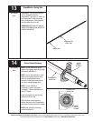
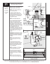
Tools Needed:
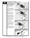
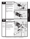
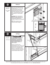
INSTALLATION
NOTE: See idrive
®
main installation and
owner’s manual for idrive
®
parts.
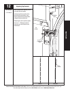
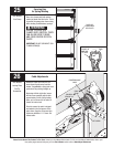
NOTE: Bring motor to the down position
by pulling the disconnect cable. Insure
opener disconnect teeth are engaged
Ibefore installing disconnect handle.
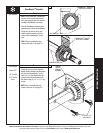
Start the #6-20 x 1/2" screw into the
disconnect handle. Thread the
disconnect cable through the top of the
disconnect handle bracket and then the
disconnect handle.
Locate the disconnect handle in full
upper position of disconnect handle
bracket.
Remove all disconnect cable slack
between the opener and the top of the
disconnect handle bracket. Tighten
#6-20 x 1/2" screw into the disconnect
handle until snug, and then tighten
screw an additional 1 to 1-1/2 turns to
secure disconnect cable to the
disconnect handle. Trim off excess cable
from bottom of the disconnect handle.
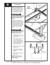
CAUTION: PULL CABLE ONLY TAUT
ENOUGH TO REMOVE THE CABLE SLACK.
PULLING THE CABLE MORE COULD
CAUSE OPENER TO DISCONNECT FROM
THE TORQUEMASTER
®
SPRING TUBE.
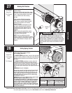
Apply emergency disconnect label next
to the mounted bracket. Use
mechanical fasteners if adhesive will
not adhere.
Using the emergency disconnect, pull
disconnect handle downwards and
place it in the manual door operated
position (Use disconnect label for
reference). Motor will be rotated 90°
from its packaged position.
If motor does not pivot 90°, see
troubleshooting section in the main
installation and owners manual of your
idrive
®
opener
Attaching Disconnect Handle
#6-20 X 1/2”
SCREW
DISCONNECT
HANDLE
BRACKET
DISCONNECT
CABLE
HANDLE
MANUAL OPERATED POSITION
UPPER POSITION
EMERGENCY DISCONNECT
LABEL
MOTOR OPERATED POSITION
Philips Head
Screwdrivers
Wire Cutters
24