


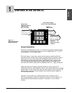
2.2 ■ Install and Wire Watlow Series 93
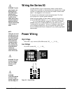
Install and Wire
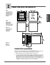
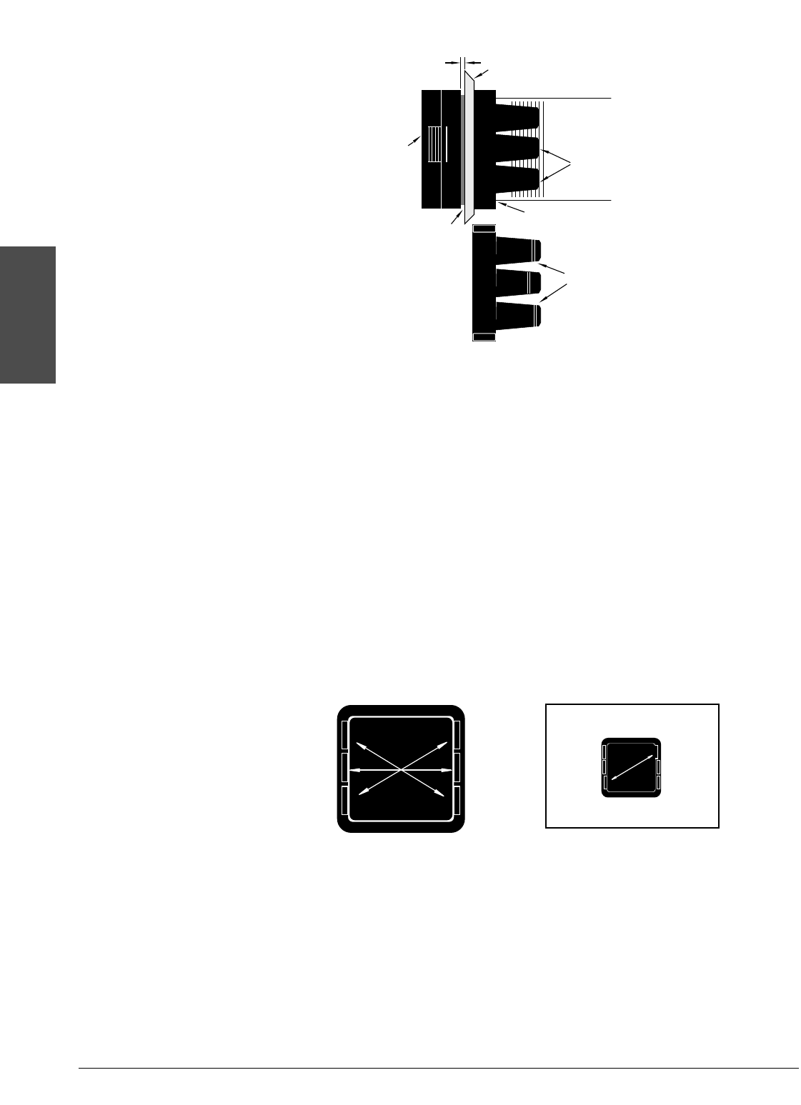
Figure 2.2a -
Mounting Case Side
View.
Figure 2.2b -
Mounting Collar
Cross Section with
offset teeth.
Figure 2.2c -
Case Rear View and
IP65 (NEMA 4X) Seal
Example.
0 to 0.483 mm space
(0 to 0.019 in.)
Bezel
Panel
External Gasket
Mounting Collar
Ridges
Teeth
Tabs
4. Insert the controller chassis into its case and press the bezel to seat it. Make
sure the inside gasket is also seated properly and not twisted. The hardware
installation is complete. Proceed to the wiring section from here.
Removing the Series 93 Controller
When removing the mounting collar, we suggest using a thin tool such as a
putty knife or screwdriver to pry gently under each of the six tabs to disen-
gage the teeth. Then rock the collar back and forth until it can be easily
pulled off the case.
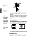
3. While pressing the front of the case firmly against the panel, slide the
mounting collar over the back of the controller. The tabs on the collar must
line up with the mounting ridges on the case for secure installation. See
Figure 2.2a. Slide the collar firmly against the back of the panel getting it as
tight as possible.
To ensure a tight seal, use your thumb to lock the tabs into place while press-
ing the case from side to side. Don’t be afraid to apply enough pressure to
install the controller. The tabs on each side of the collar have teeth which
latch into the ridges. See Figure 2.2b. Each tooth is staggered at a different
height, so only one of the tabs on each side are ever locked into the ridges at
any time.
Confirm that the tabs on one side of the collar correspond with those on the
opposite side. Make sure the two corresponding tabs are the only ones locked
in the ridges at the same time.
If the corresponding tabs are not supporting the case at the same
time, and the space between the panel and the case bezel is greater
than .019 inch, you will will not have a IP65 (NEMA 4X) seal. This
applies to units with models designated 93B. However, all units should
be mounted in this fashion to guarantee integrity of the mounting system.
IP65 (NEMA 4X) Seal Example.
Make sure that the two corresponding tabs
are locked in the ridges at the same time
.
ç
CAUTION: Follow the
installation procedure
exactly to guarantee a
proper IP65 (NEMA
4X) seal. Make sure
the gasket between
the panel and the rim
of the case is not
twisted and is seated
properly. Failure to
do so could result in
damage to equip-
ment.