


Watlow Series 93 Install and Wire ■ 2.7
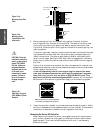
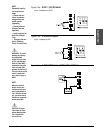
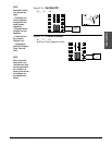
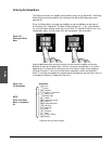
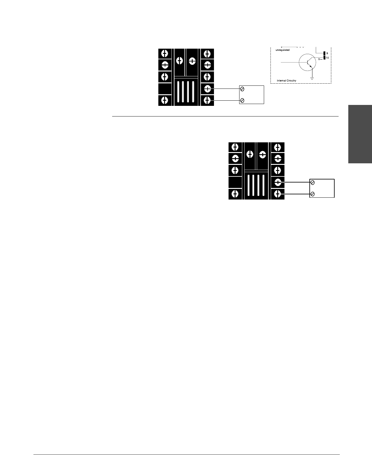
Figure 2.7a – Switched DC
93_ _- 1 C _ _- 00 _ _
Figure 2.7b – 4-20mA Process
93_ _- 1 F_ _- 00 _ _
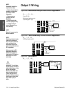
Maximum load impedance: 800Ω
External
Load
10
9
-
+
External
Load
10
9
-
+
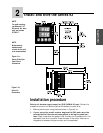
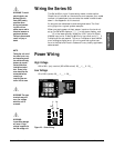
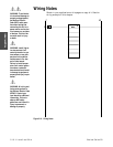
Install and Wire
NOTE:
Successful installa-
tion requires four
steps:
• Choose the con-
troller’s hardware
configuration and
model number
(Appendix);
• Choose a sensor
(Chapter Two and
Appendix);
• Install and wire
the controller
(Chapter Two);
• Configure the
controller (Chapters
Three, Four and
Five).
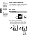
NOTE:
When an external
device with a non-
isolated circuit com-
mon is connected to
the 4-20mA or dc
output, you must use
an isolated or un-
grounded thermo-
couple.