


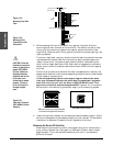
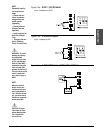
Sensor Installation Guidelines
We suggest you mount the sensor at a location in your process or system where
it reads an average temperature. Put the sensor as near as possible to the mate-
rial or space you want to control. Air flow past this sensor should be moderate.
The sensor should be thermally insulated from the sensor mounting.
See Chapter 4 for more information on DIP switch location and orientation.
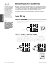
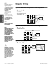
Input Wiring
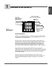
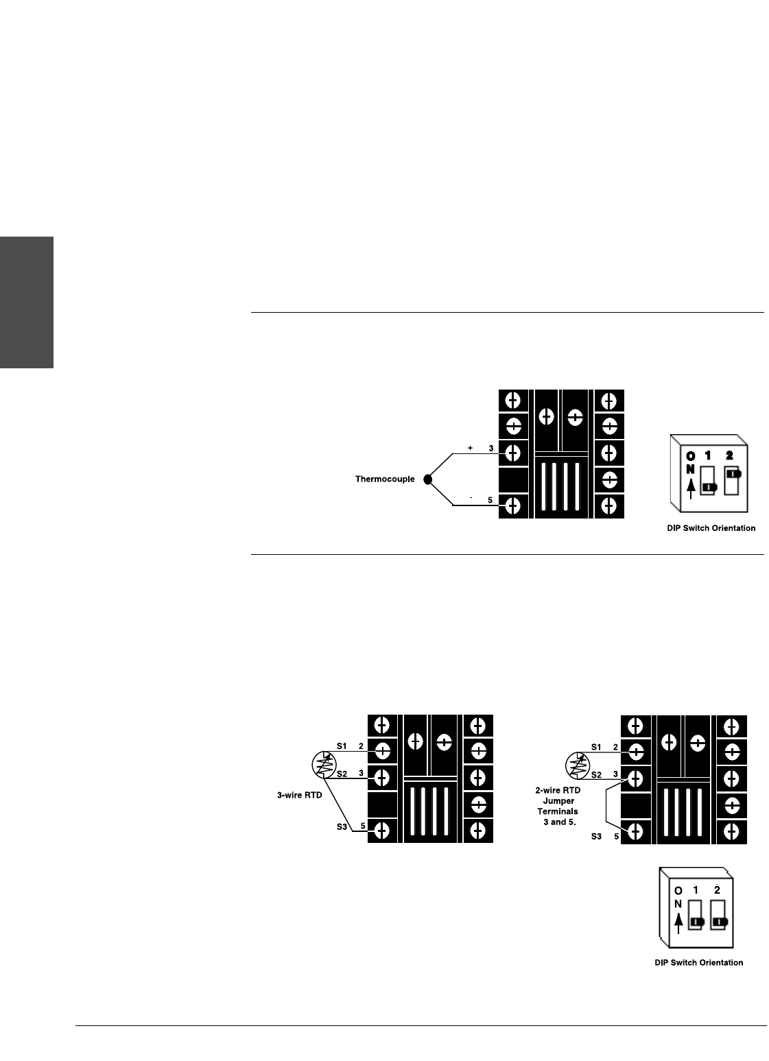
Figure 2.4a – Thermocouple
Extension wire for thermocouples must be of the same alloy as the thermo-
couple itself to limit errors.
Figure 2.4b – RTD (2- or 3-Wire) 100Ω Platinum
There could be a + 2°F input error for every 1Ω of lead length resistance
when using a 2-wire RTD. That resistance, when added to the RTD element
resistance, will result in erroneous input to the instrument. To overcome
this problem, use a 3-wire RTD sensor, which compensates for lead length
resistance. When extension wire is used for a 3-wire RTD, all wires must
have the same electrical resistance (i.e. same gauge, same length, multi-
stranded or solid, same metal).
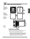
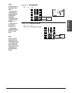
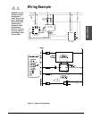
Install and Wire
2.4 ■ Install and Wire Watlow Series 93
∫ç
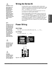
WARNING: To avoid elec-
tric shock and damage to
property and equipment,
use National Electric
Code (NEC) safety prac-
tices when wiring and
connecting this unit to a
power source and to
electrical sensors or
peripheral devices.
Failure to do so could
result in injury or death.
NOTE:
When an external device
with a non-isolated cir-
cuit common is connect-
ed to the 4-20mA or dc
output, you must use an
isolated or ungrounded
thermocouple.