


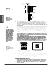
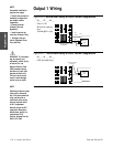
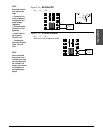
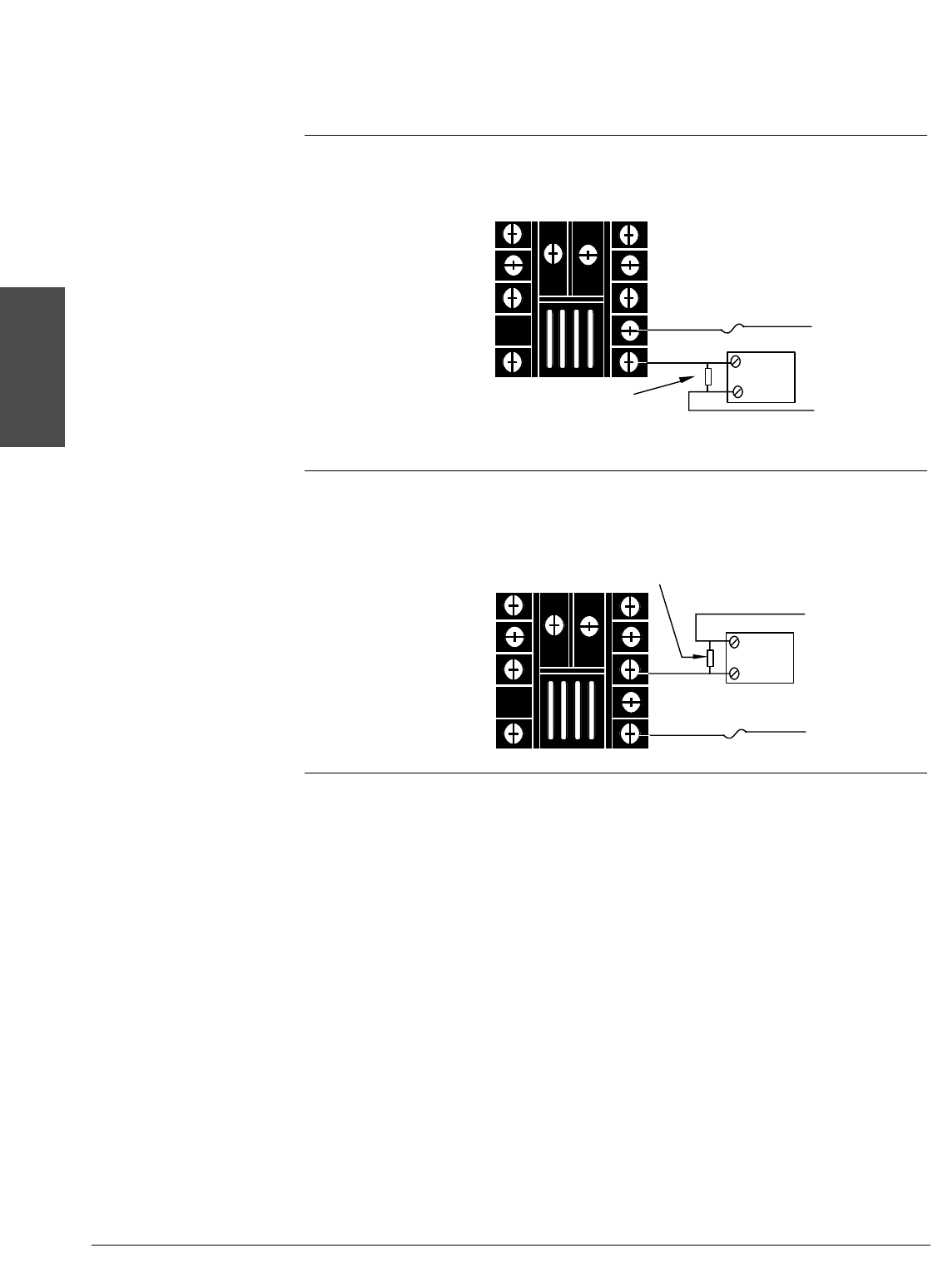
Output 1 Wiring
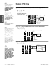
Figure 2.6a – Mechanical Relay Without Contact Suppression
93_ _- 1 D _ _- 00 _ _
Form C, 5A
Minimum load cur-
rent:
100mA @ 5VÎ (dc)
Figure 2.6b – Solid-state Relay Without Contact Suppression
93_ _- 1 K _ _- 00 _ _
0.5A (ac loads only)
8
10
L2
L1
Fuse
External
Load
Customer-supplied
Quencharc
L1
L2
8 NC
9 COM
10 NO
External
Load
Fuse
Customer-supplied
Quencharc
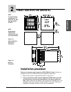
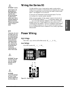
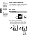
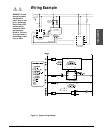
Install and Wire
2.6 ■ Install and Wire Watlow Series 93
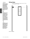
NOTE:
Successful installation
requires four steps:
• Choose the controller’s
hardware configuration
and model number
(Appendix);
• Choose a sensor
(Chapter Two and
Appendix);
• Install and wire the
controller (Chapter Two);
• Configure the con-
troller (Chapters Three,
Four and Five).
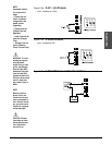
ç
WARNING: To avoid dam-
age to property and
equipment, and/or injury
or loss of life, use
National Electric Code
(NEC) standard wiring
practices to install and
operate the Series 93.
Failure to do so could
result in such damage,
and/or injury or death.
NOTE:
Switching inductive loads
(relay coils, solenoids,
etc.) with the mechanical
relay, switched dc or
solid-state relay output
options requires use of
an R.C. suppressor.
Watlow carries the R.C.
suppressor Quencharc
brand name, which is a
trademark of ITW
Paktron. Watlow Part No.
0804-0147-0000.