


Watlow Series 93 Install and Wire ■ 2.5
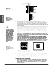
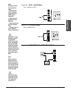
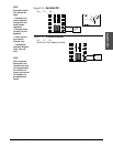
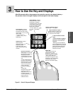
Figure 2.5a – 0-5VÎ (dc) Process
Input impedance: 10kΩ
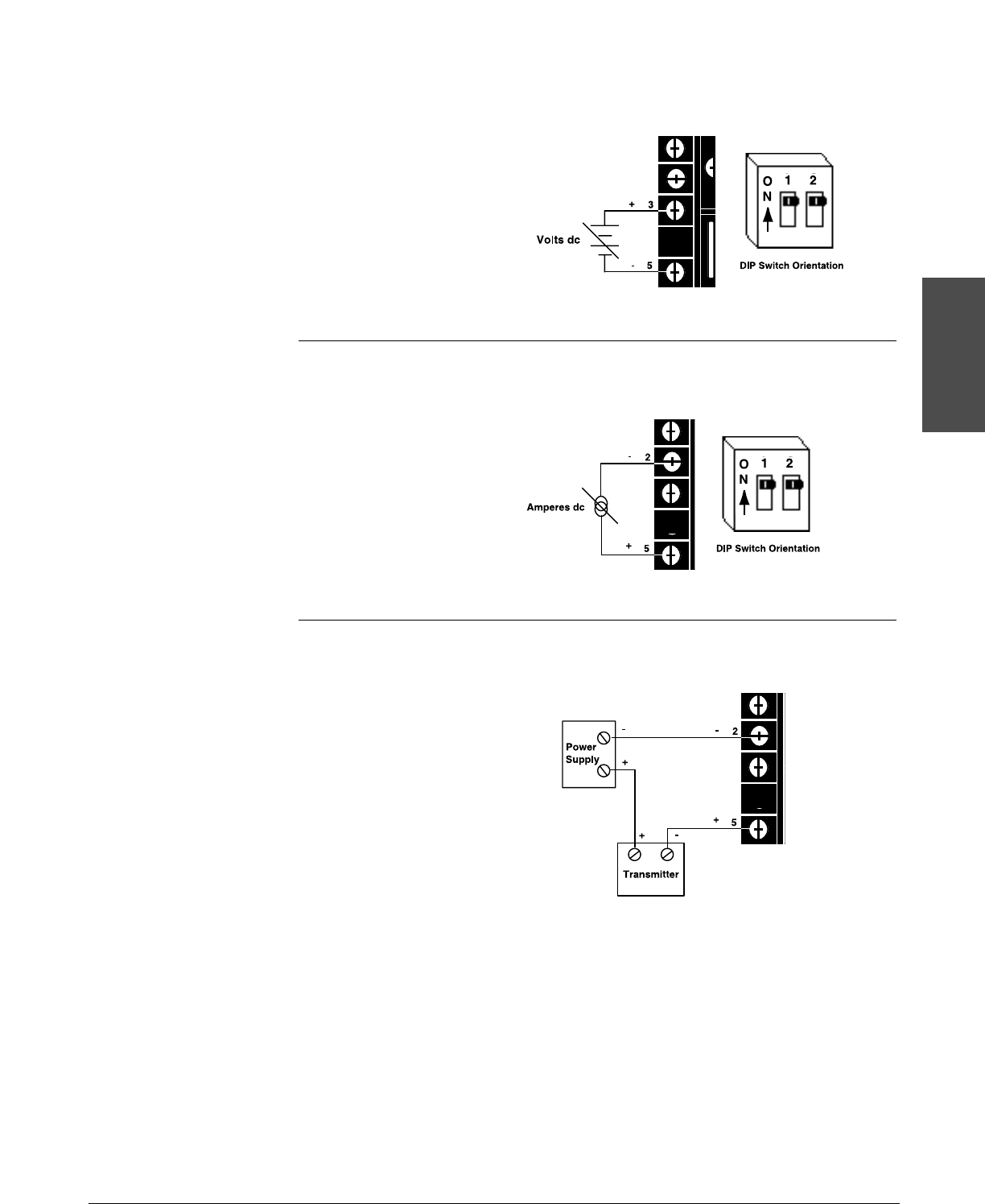
Figure 2.5b – 4-20mA Process
Input impedance: 5Ω
Figure 2.5c – 4-20mA Process: 2-Wire Transmitters
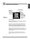
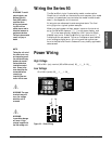
Install and Wire
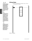
NOTE:
Successful installa-
tion requires four
steps:
• Choose the con-
troller’s hardware
configuration and
model number
(Appendix);
• Choose a sensor
(Chapter Two and
Appendix);
• Install and wire the
controller (Chapter
Two);
• Configure the con-
troller (Chapters
Three, Four and Five).
ç
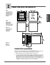
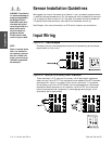
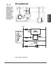
WARNING: To avoid
damage to property
and equipment,
and/or injury or loss
of life, use National
Electric Code (NEC)
standard wiring prac-
tices to install and
operate the Series 93.
Failure to do so could
result in such dam-
age, and/or injury or
death.
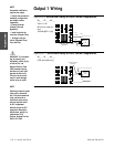
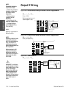
NOTE:
When an external
device with a non-
isolated circuit com-
mon is connected to
the 4-20mA or dc out-
put, you must use an
isolated or unground-
ed thermocouple.
ç
CAUTION: Process
input does not have
sensor break protec-
tion. Outputs can
remain full on.