Errors
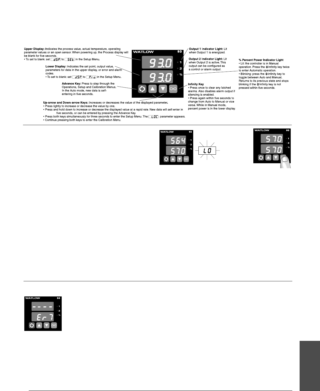
Four dashes [----] in the upper display
indicate a Series 93 error. The error code is
visible in the lower display.
[`Er2] - Sensor underrange error
(applies only to RTD units)
The sensor input generated a value lower
than the allowable signal range, or the ana-
log-to-digital circuitry malfunctioned. Enter
a valid input. Make sure the [``In] parameter (Setup Menu) and
the DIP switch settings both match your sensor.
[`Er4] - Configuration error
The controller’s microprocessor is faulty; call the factory.
[`Er5] - Nonvolatile checksum error
The nonvolatile memory checksum discovered a checksum error.
Unless a momentary power interruption occurred while the con-
troller was storing data, the nonvolatile memory is faulty. Call the
factory.
[`Er6] - Analog-to-digital underflow error
The analog-to-digital circuit is underrange. An open or reversed
polarity sensor is the most likely cause. Check the sensor; if the
connection is good and functions properly, call the factory. The ana-
log-to-digital underrange voltage is too low to convert an analog-to-
digital signal. Make sure the In parameter matches your sensor
and the DIP switches are set accordingly.
[`Er7] - Analog-to-digital overflow error
The analog-to-digital circuit is overrange. An open or reversed
polarity sensor is the most likely cause. Check the sensor; if the
connection is good, and the sensor functions properly, call the facto-
ry. The analog-to-digital overrange voltage is too high to convert an
analog-to-digital signal. Make sure the [``In] parameter (Setup
Menu) matches your sensor and the DIP switches are set accord-
ingly.
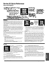
Series 93 Quick Reference
Keys and Displays
Watlow Series 93 Appendix ■ A.17
Appendix
Alarms
A process alarm sets an absolute temperature. When the process
exceeds that absolute temperature limit, an alarm occurs. The
process alarm set points may be independently set high and low.
Under the Setup Menu, select the type of alarm output with the
[`Ot2] parameter. [`PrA] sets a process alarm with alarm mes-
sage displayed. [``Pr] sets a process alarm with no alarm mes-
sage displayed.
A deviation alarm alerts the operator when the process strays
too far from the set point. The operator can enter independent high
and low alarm settings. The reference for the deviation alarm is
the set point. Any change in set point causes a corresponding shift
in the deviation alarm. [`dEA] sets a deviation alarm with alarm
message displayed. [``dE] sets a deviation alarm with no alarm
message displayed.
Example: If your set point is 100°F, and a deviation alarm is set to
+7°F as the high limit, and -5°F as the low limit, the high alarm
trips at 107°F, and the low alarm at 95°F. If you change the set
point to 130°F, the alarms follow the set point and trip at 137°F
and 125°F.
To clear an alarm:
• First correct the alarm condition, then…
• If the alarm is latching:
Clear it manually; press the ˆInfinity key once as soon as the
process temperature is inside the [`HSA] parameter alarm
limit.
• If the alarm is non-latching:
The alarm clears itself automatically as soon as the process
temperature is inside the [`HSA] parameter.
Flashing [`LO`] or [`HI`] in the lower display indicates an alarm
when [`Ot2] is set to [`PrA] or [`dEA]. The lower display
alternately shows information from the current parameter and
the [`LO`] or [`HI`] alarm message at one-second intervals.
The alarm output is de-energized and the Output 2 indicator
light is lit.
Alarm Silencing is available with the deviation alarm and has
two uses:
When [`SIL] is set to "on," the operator must manually disable
the alarm by pressing the ˆInfinity key once on initial power up
(in either the latching or non-latching mode). Alarm silencing dis-
ables the alarm output relay. However, the Output 2 indicator light
(also the lower display when [`Ot2] is set to [`dEA]) shows an
alarm condition until the process value is within the “safe” region
of the deviation alarm band. Once the process value crosses into
the “safe” region, both a latching or a non-latching alarm is ready.
Any future deviation outside this safe band triggers an alarm.
Latching: Both process and deviation alarms can be latching or
non-latching. When the alarm condition is removed a non-latch-
ing alarm automatically clears the alarm output. You must
manually clear a latching alarm before it will disappear.
Press once
to clear a
latched and
corrected
alarm.


