


32
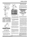
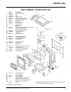
Waterford TARA T25 Direct Vent Freestanding Gas Stove
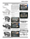
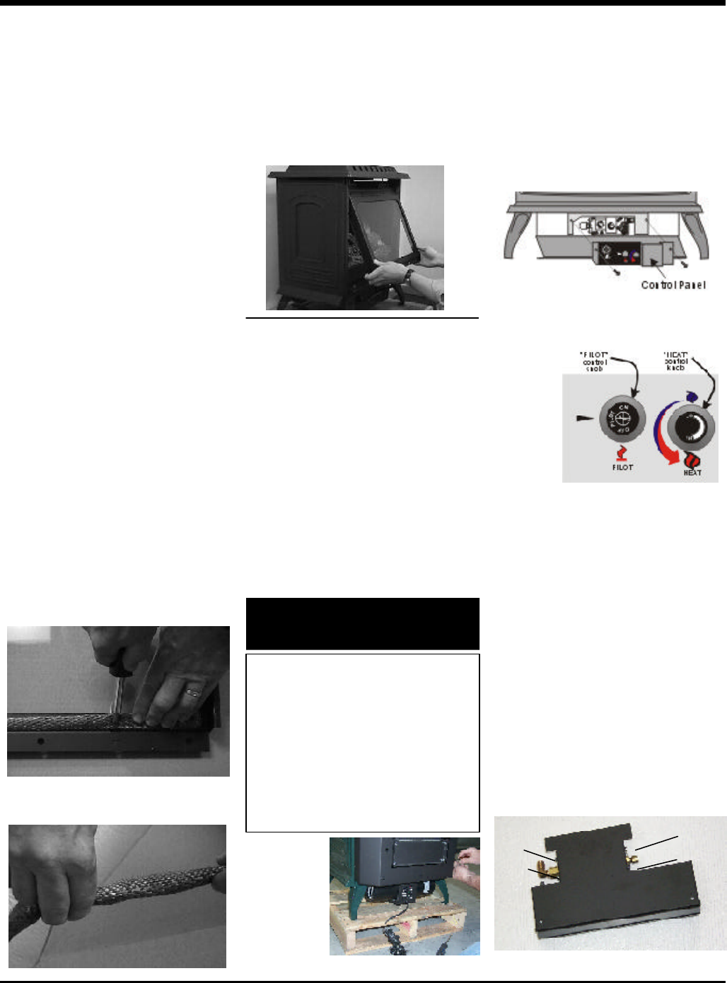
Valve Bracket with Valve - Top View
Screw
Screw
Screw
Screw
Stove Front
MAINTENANCE
VALVE MAINTENANCE
If your valve requires maintenance or replace-
ment, use the following instructions.
Note: Always close off the gas supply
before removing the valve.
1) If optional fan is installed, disconnect power
source to stove.
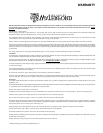
2) Remove control panel.
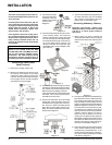
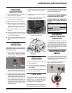
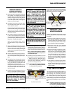
FAN MAINTENANCE
If your fan requires maintenance or replace-
ment, access to the fan is through the rear
access panel on the back of the unit. NOTE: the
unit MUST NOT be operated without the
fan access panel securely in place and
correctly sealed.
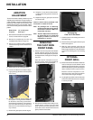
IMPORTANT: These fans collect a
lot of dust from within your home.
Ensure you maintain these fan mo-
tors on a regular basis by vacuum-
ing out the fan squirrel cages, around
the motor, and around the grills on
the back of the stove.
6) Disconnect piezo wire.
7) Remove the cast iron front panel for easier
access.
8) Remove the 4 screws holding the gas
valve assembly to the bracket.
9) Remove the thermopile wire.
10)Remove thermocouple with a 9 mm (met-
ric) wrench.
11)Remove pilot nut with an 11 mm wrench.
12)Remove valve to orifice nut with a 13/16"
wrench.
13)Remove inlet pipe with pipe wrench. Note
orientation of 90
o
elbow.
14)Remove valve and remove gas out 90
o
brass fitting. Note orientation of fitting.
Installing Valve Assembly
1) To install a new valve assembly, reverse
instructions for removing valve. See
above.
2) Check for leaks and manifold pressure.
See Gas Pressure Test instructions.
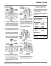
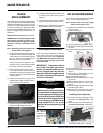
GLASS
REPLACEMENT
Your TARA stove is supplied with high temper-
ature, 5 mm Neoceram ceramic glass that will
withstand the highest heat that your unit will
produce. In the event that you break your glass
by impact, purchase your replacement door
from an authorized Waterford dealer only, and
follow our step-by-step instructions for re-
placement.
Replacement Part # W260040 Tara Glass
WARNING: Do not operate appliance with
glass panels removed, cracked or bro-
ken. Replacement of the glass should be
done by a licensed or qualified service
person.
Note: Wearing gloves will protect your
hands while handling glass.
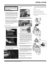
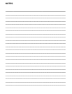
1) Remove the cast iron front panel, grasp it at
the bottom and lift the panel upwards and
out from the stove. Once free of the locating
tabs, the panel can be dropped down;
freeing it from the top of the stove.
Place the cast iron front panel on a non-
abrasive surface, away from any traffic to
ensure that it does not get damaged.
2) Remove the Front Glass Panel. Using a
7/16" socket wrench, remove the 6 hex
head bolts used to secure the glass panel
and frame to the stove. Remove the frame
and glass panel.
3) Using a flat screwdriver, pry open the 4
retaining tabs holding the glass panel in
place and remove the old glass.
4) Take the new glass and fit the 'tadpole' glass
gasket around the edge of the glass.
5) Insert the glass (with gasket) in to the frame
so that the 'bulb' portion of the gasket is
exposed.
6) Using a flat screwdriver, close the 4 retain-
ing tabs used to hold the glass in place.
7) Replace the Front Glass Panel on the stove
and reinstall the Cast Iron Front Panel.
To remove
fan: Follow the
installation in-
structions on
page 7 in re-
verse.
3) Disconnect gas line to stove.
4) Disconnect 3/8" NPT pipe from 90
o
elbow
on valve.
5) Disconnect the two (2) switch wires from
valve.
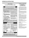
IMPORTANT
Disconnect power supply
before servicing
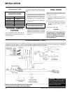
WARNING:
Electrical Grounding Instructions
This appliance is equipped with a
three pronged (grounding) plug for
your protection against shock haz-
ard and should be plugged direct-
ly into a properly grounded three-
prong receptacle. Do not cut or
remove the grounding prong from
this plug.