


Waterford TARA T25 Direct Vent Freestanding Gas Stove
15
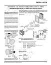
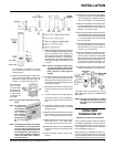
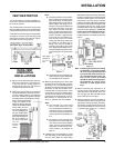
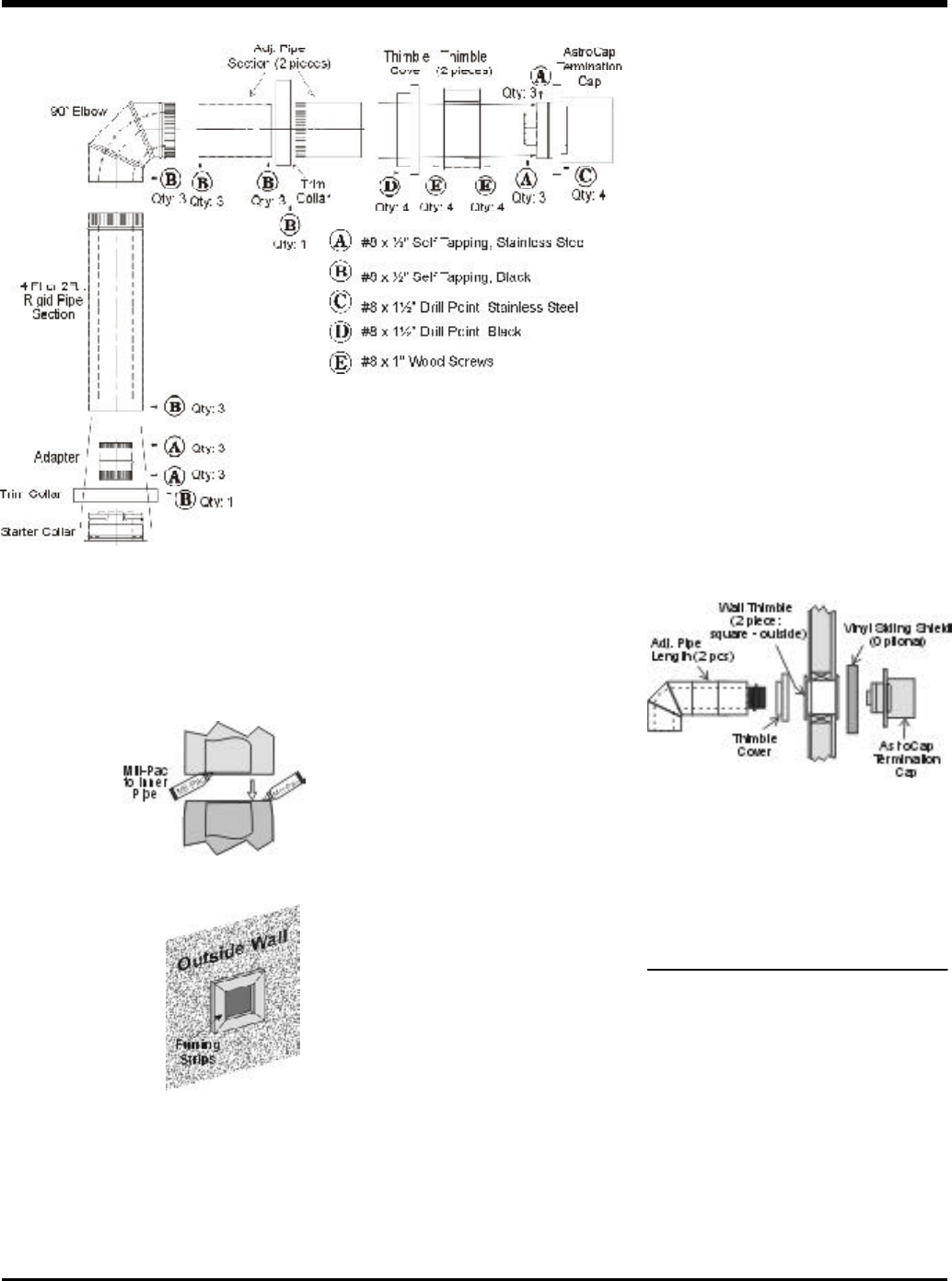
DURA-VENT
TERMINATION KIT
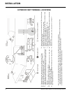
Planning Your Dura-Vent Installation
There are two basic types of Dura-Vent Direct
Vent System installations: horizontal termina-
tion and vertical termination. Confirm the max-
imum horizontal run and maximum vertical rise
from the diagram on page 18.
When planning your installation, it will be nec-
essary to select the proper length of vent pipe
for your particular requirements. For horizontal
installations, determine the minimum clearance
INSTALLATION
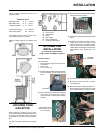
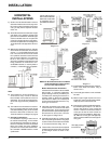
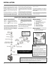
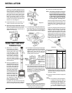
of 1-3/8"(35mm). Use Mill-Pac to seal and
secure with 3 of the #8 x 1/2" screws
(stainless steel).
4) Attach the adjustable pipe section to the
vent terminal using Mill-Pac and/or high
temperature silicone and attach with 3 of
the #8 x 1/2" screws (stainless steel).
Note: The pipe seam should be facing
down.
Note: To make the
installation
more aesthet-
ically pleasing,
we recom-
mend framing
out a square
that the cap can
be mounted
on.
Note: If installing termination on a siding
covered wall, a vinyl siding stand-
off or furring strips must be used
to ensure that the termination is
not recessed into the siding. For
vinyl siding standoff installation
refer to the Dura-Vent Termina-
tion instructions.
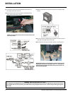
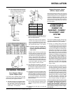
5) Slide the partially connected pipe and vent
terminal assembly through the wall thimbles
(from the exterior into the interior) and
secure the cap to the exterior wall with 4 of
the supplied screws (#8 x 1-1/2" drill point,
stainless steel). Note: pilot holes will need
to be drilled through the wall thimble on all
4 corners.
Note: The four screws provided for the
vent cap should be replaced with
appropriate fasteners for stucco,
brick, concrete, or other types of
sidings.
6) A bead of non-hardening mastic should be
run around both the termination and vinyl
siding standoff to prevent water from en-
tering and to make a tight seal between the
cap and the standoff.
7) Stretch the 4" dia. flex liner out fully and get
a trial fit of the liner onto the 4" dia. starter
collar.
8) Cut the 4" dia. flex liner to the desired size.
Hint: leave an extra 12" to 16" of length, this
will make the final assembly easier to work
with.
9) Secure the 4" dia. flex liner to the 4" adapter
with Mill-Pac and 3 of the #8 x 1/2" screws
(stainless steel).
10)Slide the decorative Thimble Cover over the
pipe sections and secure with 4 screws
(#8 x 1-1/2" drill point, black) to the wall.
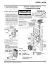
11)Slide the 90
o
elbow (crimp end up), the 45
o
elbow and the 2 ft. or 4 ft. pipe section
(crimp end up) over the 4" dia. flex liner.
12)Slide the trim collar over the adjustable pipe
sections to cover the joint of the telescopic
section.
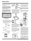
13)Install the spring spacers onto the pipe
sections.
14)Secure the 4" dia. flex liner with adapter
onto the stove collar. Put a bead of Mill-Pac
around the appliance adapter and secure
with 3 screws (#8 x 1/2, stainless steel).
15)Attach the 45
o
elbow onto the starter collar
by sealing with Mill-Pac and/or high tem-
perature silicone and securing with 3 of
the #8 x 1/2" (black) screws.
16)Attach the pipe section to the 45
o
elbow by
sealing with Mill-Pac and/or high tempera-
ture silicone and securing with 3 of the #8
x 1/2" screws (black). Pipe seams should
be facing the wall.
17)Attach the 90
o
elbow onto the pipe section
by sealing with Mill-Pac and/or high tem-
perature silicone and securing with 3 of
the #8 x 1/2" screws (black).
18)Slide the adjustable pipe section onto the
90
o
elbow. The flex may have to be com-
pressed back in order for the adjustable
pipe to properly mate to the elbow. Seal
with Mill-Pac and/or high temperature sil-
icone and secure with 3 of the #8 x 1/2"
screws (black). Pipe seams facing down.
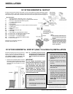
18)Install the trim collar over the starter collar
and secure with a #8 x 1/2" screw (black).
If the pipe needs to be touched up, use only
Stove Brite High Temperature Metallic Black
Stove Paint.
NOTE: All inner joints must be sealed
with Mill-Pac. All outer joints may
be sealed with high temperature
silicone.
Hint: Apply the
sealant (Mill-
Pac and/or high
temperature sil-
icone) to the out-
er pipe before
connecting the
inner pipe.