


Waterford TARA T25 Direct Vent Freestanding Gas Stove
23
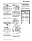
Diagram 7
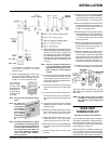
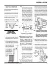
4) To determine the length of flex required,
measure from 3" (76mm) above the top of
the Flashing down to the level of the open-
ing. Add to this measurement the distance
from the center of the chimney to out through
the wall. Cut a piece of 4" flex to this length
(the flex should already be extended to its
nominal length).
5) Connect the 4" flex liner to the Top Adaptor
(Part # 985K) using 3 sheet metal screws.
Diagram 2.
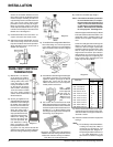
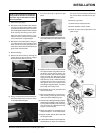
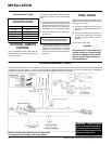
6) Feed the 4" flex liner through the Flashing
into the chimney. Continue to feed the liner
out through the opening in the masonry wall.
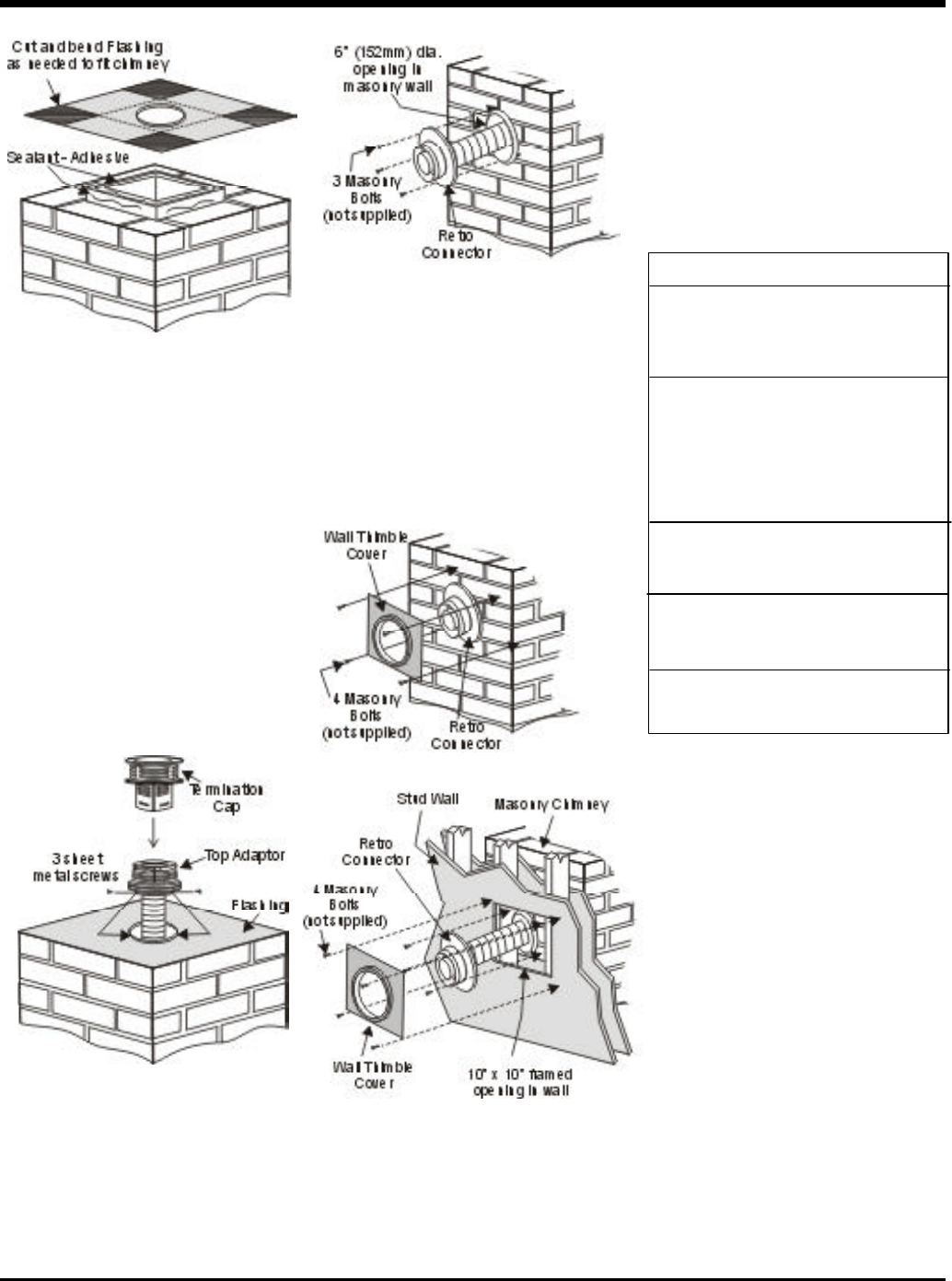
7) Secure the Top Adaptor to the Flashing. Use
3 sheet metal screws through the side of the
adaptor into the flange on the Flashing
(diagram 8). Twist lock the Termination Cap
(Part # 980 or 991) on to the Top Adaptor.
Diagram 8
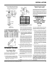
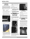
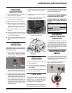
8) Attach the flex to the Retro Connector. Use
3 sheet metal screws to attach the flex liner
to the Connector. Diagram 9. Mount the
Retro Connector to the masonry wall using
masonry bolts. Re-drill larger holes on con-
nector as needed. Be careful to insure that
the connector is centered in the opening
and the mounting holes line up with the
masonry wall.
Diagram 9
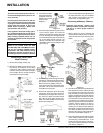
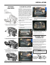
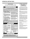
9) Slide the Wall Thimble Cover (Part # 940)
over the Retro Connector and secure with
masonry bolts. Diagram 10. If you have a
framed wall in front of the masonry, use
wood screws to mount the Wall Thimble
Cover to the framed wall, over the Retro
Connector and the 10" (254mm) square
framed opening. Diagram 11. If needed, add
a section of direct vent pipe to the Retro
Connector in order to extend through the
opening in the Wall Thimble Cover.
Diagram 10
Diagram 11
10)The connection between the appliance and
the Retro Connector may be completed with
a section of black direct vent pipe, together
with an adjustable length pipe section.
INSTALLATION
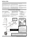
HIGH ELEVATION
This unit is approved in Canada for altitude to 4500
ft. (CAN/CGA-2.17-M91) with the resized orifice.
For Natural Gas installations above 4500 ft. follow
current CAN/CGA-B149.1.
In U.S.A., for installations above 2000 ft. refer to
current ANSI Z223.1 Sc8-8.1.2a appendix F, for
resizing orifice.
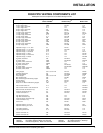
System Data - TARA T25
For 0 to 4500 feet altitude
Burner Inlet Orifice Sizes:
Natural Gas Propane
Burner #41 #53
Max. Input Rating
- Natural Gas 25,000 Btu/h
- Propane 25,000 Btu/h
Min. Input Rating
- Natural Gas 15,000 Btu/h
- Propane 13,000 Btu/h
Output Capacity
Natural Gas 18,875 Btu/h
Propane 19,250 Btu/h
Supply Pressure
Natural Gas min. 5.0" w.c.
Propane min. 12.0" w.c.
Manifold Pressure
Natural Gas 3.8" +/- 0.2" w.c.
Propane 11" +/- 0.2" w.c.