


14
Waterford TARA T25 Direct Vent Freestanding Gas Stove
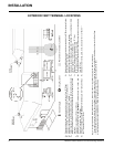
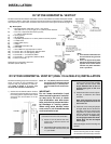
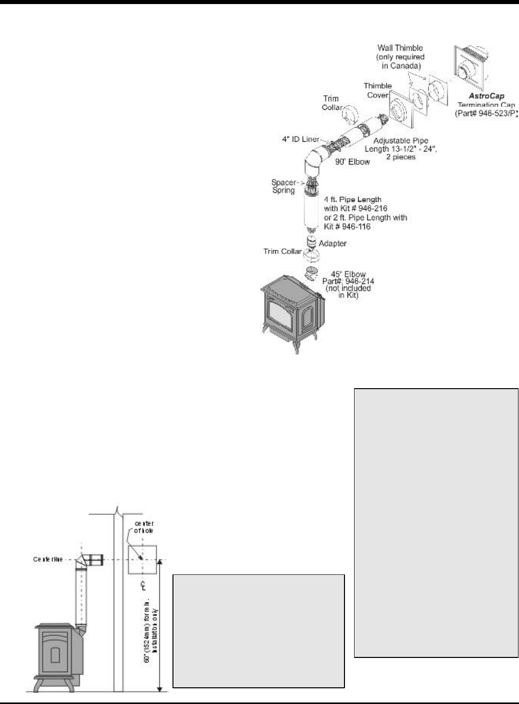
DV STOVE HORIZONTAL VENT KIT (#946-116 & #946-216) INSTALLATION
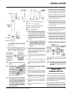
Review the following sequence of instructions
which are typical of most installations. The
sequence may vary depending on wall thick-
ness. Refer to pages 11 to 18 for vent
location and clearance dimensions.
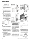
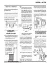
1) Set the unit in its desired location. Check to
determine if wall studs will be in the way of
the venting system, adjust location until all
clearances are met and there are no ob-
structions.
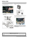
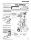
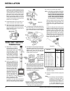
c) Attach the 2 piece adjustable pipe
section to the vent terminal and slide
into position from the exterior. The
larger diameter end of the ad-
justable pipe goes to the vent
terminal.
d) Install the 90
o
elbow onto the adjusta-
ble pipe to determine the vertical
centerline.
Note: if the centerline cannot be
met, the adjustable sections will
have to be cut.
e) Cut the 2 ft. or 4 ft. section of rigid pipe
to length. Attach the 45
o
elbow to the
rigid pipe, and ensure that the pipe
length when cut (with the 45
o
elbow)
will seat onto both the starter collar
and the 90
o
elbow. Crimped sec-
tion of rigid pipe seats into the 90
o
elbow. Only cut the uncrimped
side of pipe.
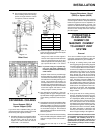
Dismantle all pipe sections including vent
terminal.
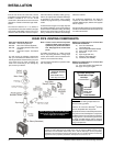
3) Attach the 4" dia. flex liner to the vent
terminal ensuring that the flex overlaps
the collar of the vent terminal by a minimum
Note: A 1-1/2"(38mm) clearance around
the outer pipe must be maintained
except that only a 1" (25mm) clear-
ance is needed at the termination
end.
IMPORTANT:
Do not locate termination hood
where excessive snow or ice build-
up may occur. Be sure to check
vent termination area after snow
falls, and clear to prevent acciden-
tal blockage of venting system.
When using snow blowers, make
sure snow is not directed towards
vent termination area.
2) Assemble a trial fit to determine the ver-
tical center-line for the vent termination.
a) Cut a 9-1/2" x 9-1/2" (241mm x 241 mm)
square hole on both the interior and
exterior wall.
b) Install wall thimbles on both interior and
exterior wall with 4 wood screws (#8
x 1") per thimble.
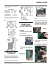
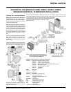
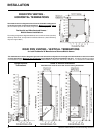
DV STOVE HORIZONTAL VENT KIT
DV Stove Horizontal Vent Kit (2 ft. Part # 946-116 or 4 ft. Part # 946-216) includes all the parts needed
to install the U29-2 or U45-3 with minimum horizontal and vertical vent dimensions. For installations
that require longer vertical and/or horizontal vents use the Dura-Vent system as shown on page 18.
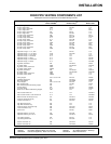
Qty. Description
1) 1 Rigid Pipe Section (Kit # 946-116: 2 ft. (1.2m) length,
Kit # 946-216: 4 ft. (1.2m) length), 6-1/2" (165mm) inside diameter
2) 1 Flex Liner, compressed aluminium 2 ply liner,
4" (102mm) inside diameter
3) 4 spring spacers
4) 1 90 deg. Elbow
5) 1 Adjustable pipe section 13-1/2" to 24" (343mm x 610mm), 2 pieces
6) 1 Thimble Cover
7) 1 Wall Thimble (2 pcs.)
8) 1 Adapter
9) 1 AstroCap Termination Cap
10) 2 Trim Collar
11) 1 tube of Mill-Pac, high temperature sealant
12) 12 Screws, #8 x 1/2" Self tapping, Stainless Steel
13) 14 Screws, #8 x 1/2" Self tapping, Black
14) 4 Screws #8 x 1-1/2" Drill Point, Black
15) 4 Screws #8 x 1-1/2" Drill Point, Stainless Steel
16) 8 Wood screws #8 x 1"
Required but not included in above Kit:
45
o
Elbow (Part #: 946-214)
Note:
a) Liner sections should be con-
tinuous without any joints or
seams.
b) This is an approved system,
therefore components in this
system must not be substi-
tuted for any other manufac-
turer's products.
INSTALLATION