


VIVOTEK
User's Manual - 15
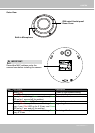
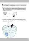
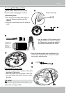
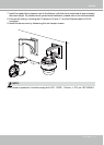
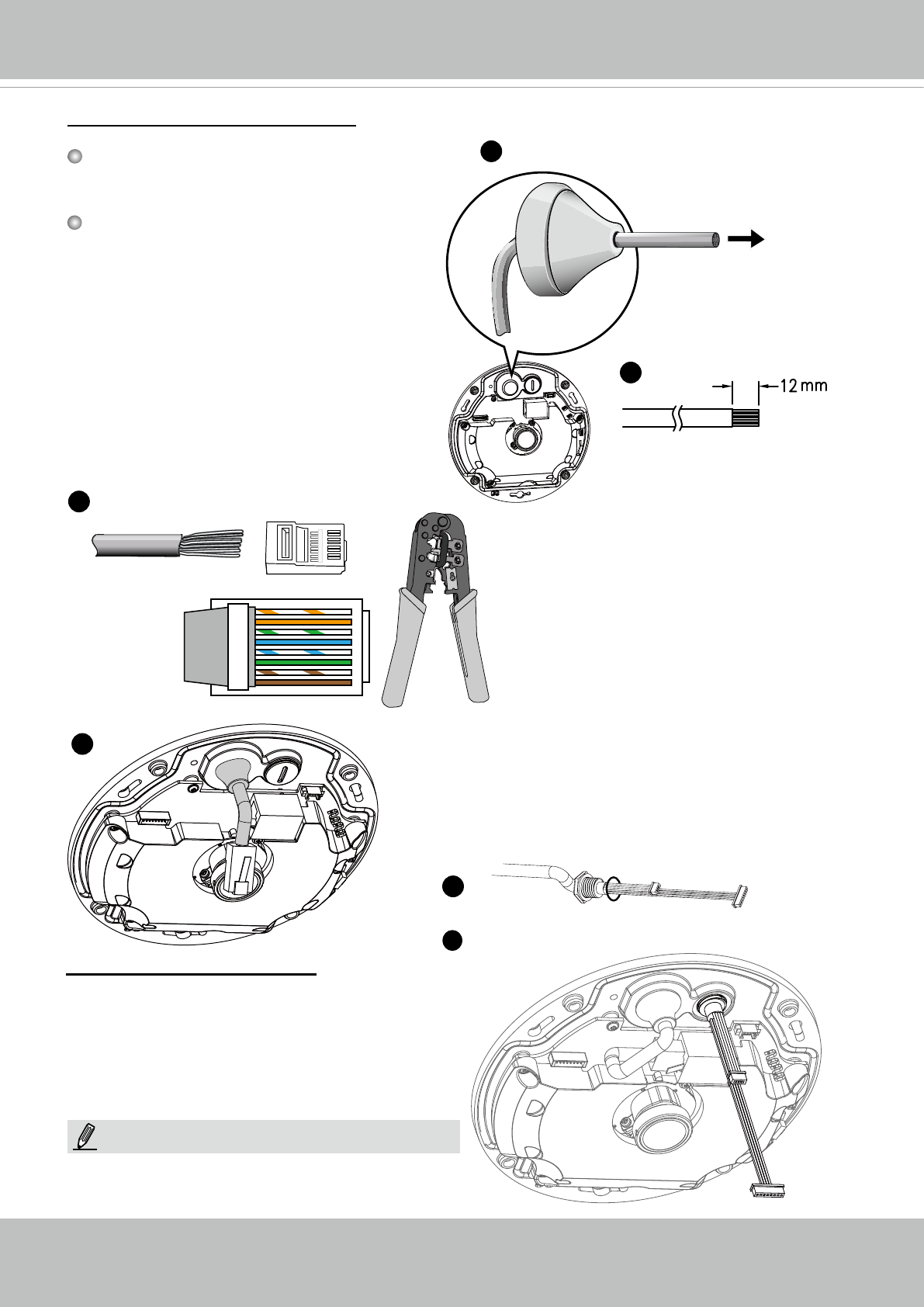
RJ45 Cable Dimension (unit: mm)
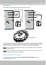
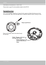
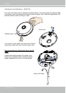
Assembly Steps
1. Drill a hole on the rubber seal plug and
insert an Ethernet cable through the
opening.
2. Strip part of the sheath from the Ethernet
cable.
Recommended cable gauge: 5 to 8mm
Connecting RJ45 Ethernet Cable
Rubber Seal Plug
1
2
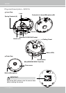
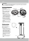
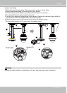
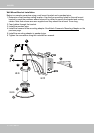
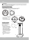
Connecting DC Power Cable
1. Add the supplied rubber washer to the cable
as shown in the picture.
2. Feed the cable from the bottom of the cam-
era and tighten the plastic base for water-
proong.
1
2
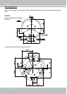
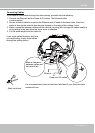
3. You will need an RJ45 crimping tool to
attach the Ethernet wires to a connec-
tor. When done, connect the cable to
the camera’s Ethernet RJ45 socket.
o
O
g
B
b
G
br
BR
1
2
3
4
5
6
7
8
3
4
4. Feed the Ethernet cable from the bottom of the
camera and through the hole. Attach the rubber
seal plug for water proong.
o: white/orange stripe
O: orange solid
g: white/green stripe
B: blue solid
b: white/blue stripe
G: green solid
br: white/brown stripe
BR: brown solid
Connect the supplied power & IO cables if your
switch does not support PoE.
NOTE: