


PKG-PRC010-EN
Mechanical
Specifications
46
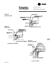
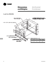
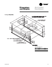
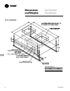
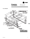
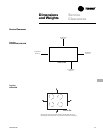
Deluxe Self-Contained
SCRB/SIRB/SCWB/SIWB
Cabinet
The unit framework is heavy gauge
welded steel construction. Exterior panels
are fabricated from 18-gauge zinc coated
galvanized steel. The unit exterior is
cleaned, phosphatized, and painted with
an air-dry enamel finish. The fan and
compressor sections are insulated with
¾-inch (19 mm) one-pound (0.5 kg)
density fiberglass insulation.
The unit is provided with removable
panels to allow service access to com-
pressors, condensers, fan motor, bear-
ings, coils, and valves. Knockouts are
provided on both sides of the unit to allow
electrical power, control wiring, piping
connections, and fan shaft removal (10
and 15-ton units only). A decorative
return air grille is provided on all 3, 5 and
7.5 ton units. The 10 and 15-ton cabinet
separates into two sections for conver-
sion into a horizontal configuration. This
configuration has front and back access
panels on the coil and compressor
sections and front and back access to the
blower section.
Compressors
The 3, 5, and 7.5 ton units have a single
compressor and 10 and 15-ton units have
dual compressors. Compressors are
hermetic 3600 rpm motors with crank-
case heaters as standard. Each compres-
sor has its own independent refrigerant
circuit. The compressors are protected
with internal motor winding temperature
cutouts and are mounted on rubber-in-
shear isolators for vibration isolation.
Condenser (Water-Cooled)
The condenser is a shell and coil design
with a finned, copper, inner tubing, and a
steel outer shell. Piping connections are
from either side of the unit. Each refriger-
ant circuit is provided with a separate
condenser or pair of condensers. Con-
denser waterside working pressure
cannot exceed 400 psig.
Evaporator
The evaporator coil is constructed of
seamless copper tubes expanded into
aluminum fins. Tubes are
3
/
8
-in (9.5 mm)
OD with internally enhanced surfaces.
Coils are factory leak tested to 475 psig.
The drain pan is galvanized steel. Knock-
outs are provided on both sides of the
unit for condensate removal.
Refrigerant Circuit (Water-Cooled)
Refrigerant circuits are independent and
completely piped including filter driers,
distributors and thermal expansion
valves with non-adjustable superheat.
The circuits are leak-tested, dehydrated,
and charged with oil and Refrigerant-22
at the factory. Shrader access valves are
provided in the suction and liquid lines.
Refrigerant Circuit (Air-Cooled)
Refrigerant circuits are independent and
completely piped including distributors
and thermal expansion valves with non-
adjustable superheat. The circuits are
leak tested, dehydrated, and charged
with oil and nitrogen at the factory.
Shrader access valves are provided in
the suction and liquid lines.
Supply Fan
The 3, 5 and 7.5 ton units have a single
supply fan and the 10 and 15-ton units
have two supply fans. Supply fans are
forward curved centrifugal-type. The 10
and 15-ton units are secured to a solid
steel shaft with permanently lubricated
bearings. The drive components include
variable pitch sheaves and V-belts. The
supply fan motor is an open drip-proof
type with a standard NEMA frame,
permanently lubricated motor bearings,
and a service factor of 1.00 minimum.
The fan wheel is dynamically balanced at
the factory.
Filters
One-inch throwaway filters are installed
in the coil section of the unit.
Unit Controls
All units are provided with a terminal
block.
Agency Listing
The unit has the US Underwriter’s
Laboratory agency listing and/or the
Canada CSA agency listing.
Deluxe Self-Contained
Options
Protective Coating
Unit
The unit’s exterior and exposed interior
shall have a four to six mil coat protective
coating.
Coil
The evaporator coil shall have a corrosion
protective coating consisting of a conver-
sion layer and a polyurethane top layer
applied to protect in harsh environments.
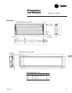
Hydronic Heating Coils
Hot Water
The hot water coil shall be a two-row,
type WC heating coil and is field installed
inside the unit’s cabinet.
Steam
The 3, 5, and 7.5-ton steam coil shall be a
one-row, type SDS heating coil. The 10
and 15 ton steam coil shall be a one-row,
type NS heating coil. Steam coils shall be
field installed inside the unit’s cabinet.
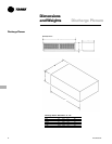
Discharge Plenum
The discharge plenum shall be provided
with double deflection louvers to provide
horizontal discharge.
Cupro-Nickel Condenser
The condenser shall be shell and coil
design with 90-10 cupro-nickel inner
tubing. Piping connections shall be made
from either side of the unit. Each refriger-
ant circuit shall be provided with a
separate condenser or pair of condens-
ers. Condenser waterside working
pressure shall be 400 psig.
Permanent Filter
One-inch permanent filters shall be
provided for field installation in the coil
section of the unit.
Return Air Grille
A decorative return air grille shall be
provided for field installation on 10 and
15-ton units.
Oversized Fan Motor Kit
Oversized fan motors and drive kits shall
be available for those applications where
external static pressure exceeds the
capability of the standard fan motor.
Water Regulating Valve
A water regulating valve shall be pro-
vided for each condenser circuit to control
condensing pressure. The
3
/
4
-inch valve
includes a capillary tube adapter fitting to
connect the liquid line Shrader valve. The
water regulating valve drops the water-
side operating pressure to 250 psig.