


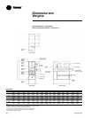
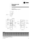
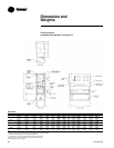
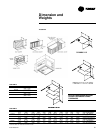
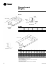
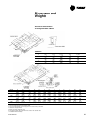
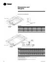
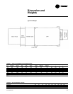

MUA-PRC001-EN36
Mechanical
Specifications
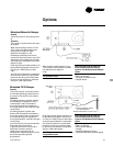
General
The BASIC unit is factory-assembled,
wired and test-fired. DEPENDING ON
THE OPTIONS, UNIT MAY SHIP IN
SECTIONS DUE TO PHYSICAL SIZE
OF EQUIPMENT. Although designed
primarily for outdoor mounting, it can be
mounted indoors. Units are mounted on
steel rails with lifting lugs, which make
them suitable for curb or slab mounting.
Units are available for operation on
either natural or LP (propane) gas.
Casing
Basic unit casings are fabricated
of die-formed galvanized steel.
Unit sizes 109-220 shall be 18-gauge.
Unit sizes 225-230 shall be 18-gauge,
except exterior walls which are
16-gauge.
Access doors are hinge-mounted with
industrial-type hardware for easy access
to service compartments.
All casings shall be airtight and
weatherproof. Complete access shall be
provided to all components through
gasketed access doors or panels. This
includes the motor, blower, burner,
electrical components, and manifold
sections.
Fans
Supply fans shall be double width,
double inlet centrifugal type with FC fan
wheels. Fans are tested in accordance
with AMCA 210. The fan or fans shall be
mounted on a heavy-duty polished steel
shaft designed for a maximum operating
speed not to exceed 75 percent of its first
critical speed. Bearings are to be heavy-
duty, industrial prelubricated type.
Bearing life is 100,000 hours.
Blowers are driven by a V-belt package
sized with a capacity of 25 percent
greater than the motor horsepower.
Multiple belt applications will be
matched sets. Drives are adjustable
pitched diameter type up through 7½ hp,
fixed on motors over 7½ hp.
Burner Section
The burner section shall contain a
Maxon NP burner constructed of rust-
resistant cast iron bodies (which serve as
the gas manifold) drilled to discharge the
fuel between diverging #321 stainless
steel mixing plates. The entire burner
assembly is mounted directly in the air
stream being heated. The fresh air
stream passes through the mixing plates
and mixes with the fuel as combustion
air; thus, all available heat from the
gaseous fuel is released directly into the
air stream. Air velocities across the
burner assemblies are established by the
use of profile plates.
The manifold is located outside of the
airstream and shielded from
atmospheric conditions by means of a
protective compartment with hinged
access. An observation port shall be
located to provide view of the pilot and
main flame.
Units shall be supplied with a wide-
range burner with a modulating
turndown ratio of 25 to 1. Adjustable
profile plates shall be provided and sized
to maintain the required velocity across
the line burner. The operation of the
burner shall be programmed through
the flame safeguard with timed prepurge
and flame sensing.
Control Enclosure
Units shall be provided with a control
compartment. All controls mounted
within this compartment are to be wired
to a numbered terminal strip.
All wiring is to be color coded and in
accordance with NEC. A circuit diagram
of the approved electrical drawing shall
be provided with the unit. All electrical
components shall bear the UL label.
Controls
Unit controls shall consist of a spark
ignition system with a flame rod sensing
the flame, a high temperature limit
switch set at 185 F, a flame safeguard
with alarm contacts, ignition
transformer, air proving differential
switch, timed freeze protection, and a
series 14 or 44 modulating control
system.
The unit shall also contain a main fan
starter and overloads, control circuit
fuses, and vents for outdoor units.
Gas Train Approvals
The standard gas train consists of a main
manual gas shutoff valve, a motorized
electric main gas valve,
the Maxitrol modulating gas valve,
a manual pilot gas shutoff valve, a
manual pilot gas pressure regulator, a
pilot gas valve, an orificed needle valve,
and an auxiliary gas valve.
The Factory Mutual (FM) gas train
consists of a manual main gas shutoff
valve, a motorized electric main gas
valve, the Maxitrol modulating gas valve,
a manual pilot gas shutoff valve, a
manual pilot gas pressure regulator, a
pilot gas valve, an orificed needle valve,
a high/low gas pressure switch, a
manual auxiliary gas shutoff valve, and
an auxiliary gas valve. (Optional)
The Industrial Risk Insurers (IRI) gas train
consists of a manual main gas shutoff
valve, a motorized electric main gas
valve, the Maxitrol modulating gas valve,
a manual pilot gas shutoff valve, a
manual pilot gas pressure regulator, a
pilot gas valve, an orificed needle valve,
a high/low gas pressure switch, a
manual auxiliary gas shutoff valve, a
normally open vent valve, and an
auxiliary gas valve. (Optional)