


MUA-PRC001-EN22
Dimension and
Weights
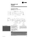
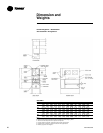
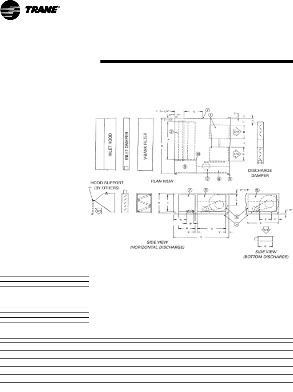
Inlet Hood Support (By Others)
• The purpose of hood support is to
support the weight of the unit
accessories which are attached to the
inlet of the basic unit.
• The hood support can be made from
two, 2” x 2” x ¼” angle iron.
• One angle iron support should be
located in, or close to, the outer corners
of the hood. The supports can be bolted
to the hood.
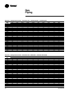
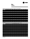
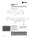
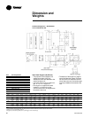
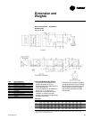
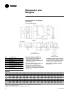
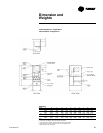
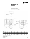
Horizontal Arrangement — Double Blower
Return Air Opening Downstream of Burner
Motorized Return Air Damper — Motorized 75/25 Damper
215 218 220 222 225 230
Table DW-4
Model A B C E F G H J L M N P R S T U W X Y
215 3' 0" 7' 10" 6' 5" 1' 4" 1' 0-
3/8
" 1' 7-
7/8
"7-
1/8
" 1' 10-½" 7-
7/8
" 1’6-
15/16
" 1' 7" 5' 5-¾" 1’9” 2’9” 2’5” 1’9” 1' 2-
¼
" 4-½" 5-¾"
(914) (2388) (1956) (406) (314) (505) (181) (572) (200) (481) (483) (1670) (533) (838) 737) (533) (362) (114) (146)
218 3' 0" 7' 10" 6' 5" 1' 7" 1' 0-
3/8
" 1' 7-
7/8
"7-
1/8
" 1' 4" 7-
7/8
" 1’10-
1/16
" 1' 7" 5' 5-¾" 1’9” 2’9” 2’5” 1’9” 1' 2-¼" 4-½" 5-¾"
(914) (2388) (1956) (483) (314) (505) (181) (406) (200) (560) (483) (1670) (533) (838) 737) (533) (362) (114) (146)
220 4' 0" 10' 10" 8' 0" 2' 0-
7/8
" 1' 1-
3/16
" 2' 4-¼" 11-½" 2' 5-½" 1' 0-
3/8
" 2’1-
1/16
" 1' 7" 7' 3-
3/8
" 2’9” 3’2” 3’3” 2’7” 1' 2-¼" 0' 8" 7-
1/8
"
(1219) (3302) (2438) (632) (335) (718) (292) (749) (314) (637) (483) (2219) (838) (965) (991) (787) (362) (203) (181)
222 4' 0" 10' 10" 8' 0" 2' 3-
3/8
" 1' 1-
3/16
" 2' 4-¼" 11-½" 2' 0-
5/8
" 1' 0-
3/8
" 2' 3-
9/16
" 1' 7" 7' 3-
3/8
" 2’9” 3’2” 3’3” 2’7” 1' 2-¼" 0' 8" 7-
1/8
"
(1219) (3302) (2438) (695) (335) (718) (292) (625) (314) (700) (483) (2219) (838) (965) (991) (787) (362) (203) (181)
225 5' 0" 12' 10" 8' 0" 2' 7-
3/8
" 1' 5-
9/16
" 3' 1-¾" 1' 2-½" 3' 1-
5/8
" 1' 3-
3/8
" 2' 7-½" 11-
13/16
" 9' 3-
3/8
" 2’1-¾” 3’2” 4’3” 1’8” 1' 8-¼" 1' 2" 6-¼"
(1524) (3912) (2438) (797) (446) (959) (368) (956) (391) (800) (300) (2829) (654) (965) (1295) (508) (514) (356) (159)
230 5' 0" 12' 10" 8' 0" 3' 0-
7/8
" 1' 5-
9/16
" 3' 1-¾" 1' 2-½" 2' 2-
5/8
" 1' 3-
3/8
" 3' 1" 11-
13/16
" 9' 3-
3/8
" 2’1-¾” 2’9” 4’3” 1’8” 1' 8-¼" 1' 2" 6-¼"
(1524) (3912) (2438) (937) (446) (959) (368) (676) (391) (940) (300) (2829) (654) (838) (1295) (508) (514) (356) (159)
Notes:
1. To permit blower shaft replacement, the side opposite the controls should have clearance equal to the unit width.
2. Minimum of 5’ for serviceability clearance.
3. Supply duct connection (by others) to be “pants-legged”from unit discharge.
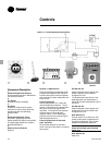
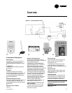
Item Unit Components
1 Centrifugal Supply Fan
2 Fan Motor
3 Heat Source (Line Burner)
4 Control Cabinet
5 Hinged Control Cabinet Access Door
6 Motor and Drive Access Plate
7 Access Door
8 Removable Suspension Lifting Lug
9 Manifold Compartment
10 Observation Port
11 Unit Base
• The bottom of the angle iron support
should be fitted with a base. The base
can sit on the roof and does not have
to be fixed to the roof. An isolation pad
may be put between the base and the
roof.