


41MUA-PRC001-EN
Options
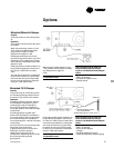
Exhaust Interlock
The exhaust interlock is a pair of contacts
on the unit that will close when the unit
is “on.” The customer can wire the
exhaust fan to the contacts so that when
the heating unit is “on,” the exhaust fan
will also be “on.” Note the heating unit
turns on the exhaust fan.
The auxiliary contacts on the fan motor
starter are the contacts which are used
as the exhaust interlock. The auxiliary
contacts are wired to the numbered
terminal strip. The customer can wire the
indicated terminals into the control
circuit of the exhaust fan.
Note: If the customer wants the exhaust
fan to turn the heating unit “on,” he/she
has to provide a pair of contacts that will
close when the exhaust fan is “on.”
Interlocking Relay
The interlocking relay is two pair of
contacts, one normally open and the
other normally closed. The contacts
switch positions when the unit is “on.”
The contacts are wired to the numbered
terminal strip. The customer can wire a
wide range of devices to the interlocking
relay by wiring to the indicated
terminals.
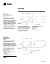
Seven Day Timeclock/
Night Setback Thermostat
The seven day timeclock is used
primarily for either one of the following:
1
Start and stop the unit at preset times
Example: A building is occupied at
8:00 AM. At 4:30 PM, people leave the
building. The timeclock could be set to
turn the unit on at 7:30 AM and off at
5:00 PM.
2
The timeclock can be used with an on-off
night setback thermostat (NSB
thermostat). The timeclock and NSB
thermostat would be wired so that
during the night, the NSB thermostat
would turn the unit on and off.
Example: Same as example above, only
at 5:00 PM the NSB thermostat would
turn the unit on and off. If the
temperature in the space fell below the
setting of the NSB thermostat, the unit
would come “on.” If the temperature
rose above the setting, the unit would go
“off.”
Inlet On-Off Duct Stat
Automatically turns burner off when inlet
air temperature equals setting of control.
Works as a lockout for the burner.
Example: If we want the burner to be
“off” if the entering air temperature is
65 degrees, the inlet on-off duct stat
would be set at 65 degrees.
Without the inlet on-off duct stat, if the
fan switch and heat switch are both “on,”
no matter how warm the incoming air,
the burner will go as low as low fire, but
will not go “off.”
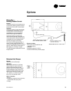
UV Flame Sensor (UV Mini-Peeper)
Flame sensor checks to make sure the
pilot flame has ignited before gas is sent
to the main burner. Operates by sensing
the light of the pilot flame.
If the flame sensor does not sense the
pilot flame, the unit shuts down (fan and
burner go off) and the flame failure light
on the optional remote panel
goes on.
The unit has to be reset by pushing the
reset button on the burner relay.
Differences between UV Flame Sensor
and Flame Rod:
Both are used for the same purpose —
to check if the pilot flame is on. The
flame rod is “standard.” The UV sensor
needs to be ordered as an option.
If condensation forms on the flame rod
while the unit is off, it may give a false
signal and prevent the unit from coming
on. The wet flame rod does not sense
the pilot flame and shuts the unit down.
This nuisance tripping can be avoided
with the UV flame sensor.
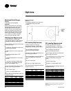
Optional Gas Controls
Series 14 — Constant Discharge
Temperature
The constant discharge temperature, gas
modulating control system consists of
the Maxitrol electronic gas modulating
system (55 to 90 F range), which includes
a discharge air sensor located in the
blower discharge, a modulator/regulator
valve mounted in the gas piping
manifold, an amplifier installed in the
electrical control panel, a 115 to 24 volt
transformer, and a remote temperature
selector.
Series 44 — Space Temperature Control
The space temperature control, gas
modulating control system consists of
the Maxitrol electronic gas modulating
system, which includes a Series 44
discharge air sensor (55 to 90 F range)
mounted in the blower discharge, a
modulator regulator valve mounted in
the gas piping manifold, an amplifier
installed in the electric control panel, a
115 to 24 volt transformer, and a
Selectrastat mounted in the area where
the temperature is to be sensed.