


MUA-PRC001-EN16
Controls
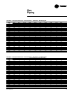
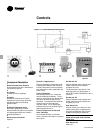
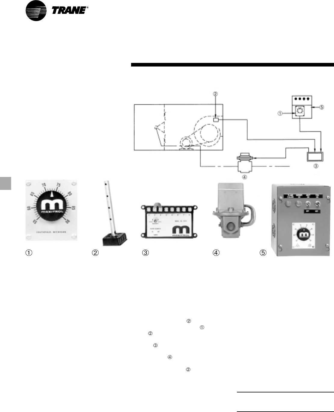
Component Description
1
Remote Temperature Selector
Not temperature sensitive. Mounted on
remote control station.
2
Air Sensor
Installed in blower discharge.
3
Amplifier
Installed in electrical control panel.
Contains wiring terminals, sensitivity
adjustments and one calibrating
potentiometer.
4
Modulator/Regulator Valve
Mounted in gas piping manifold.
Receives electrical signal from amplifier
and adjusts gas pressure to maintain
desired temperature.
5
Remote Control Station
Optional
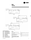
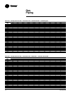
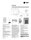
System 14 — Constant Discharge Air Temperatures
System 14 Applications
Controls discharge air temperature with
instantaneous response and is ideal for
industrial areas and commercial spaces
such as kitchens, hotels, restaurants and
boiler rooms.
Control Operation
Desired temperature at is set at the
remote temperature selector . The air
sensor senses leaving air temperature
and sends an electrical signal to the
amplifier . The amplifier then sends an
electrical signal to the modulator/
regulator valve , which adjusts gas
pressure to the burner, maintaining the
desired temperature at .
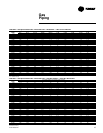
Control Sequence with Fan and
Heat Switches
Fan and heat switches are included
when a remote control station is ordered
as an option.
Fan Switch On
Optional damper opens, damper end
switch closes, fan motor starter is
energized, fan runs.
The freeze-stat will stop the fan if the
discharge leaving air temperature is
below 45 F, three minutes after the fan is
turned on.
Fan Switch Off
Optional damper closes, damper end
switch opens, fan motor starter is de-
energized, fan is off.
Heat Switch On
If the fan switch is on, and the air flow
switch closes, power is applied to the
flame failure safeguard relay to begin
predetermined ignition sequence.
Note: The fan switch must be on, or the
burner will not light, even if the heat
switch is on.
Heat Switch Off
Heat is off.
Optional