– 167 –
No.
Part name
Fan guard
Procedure
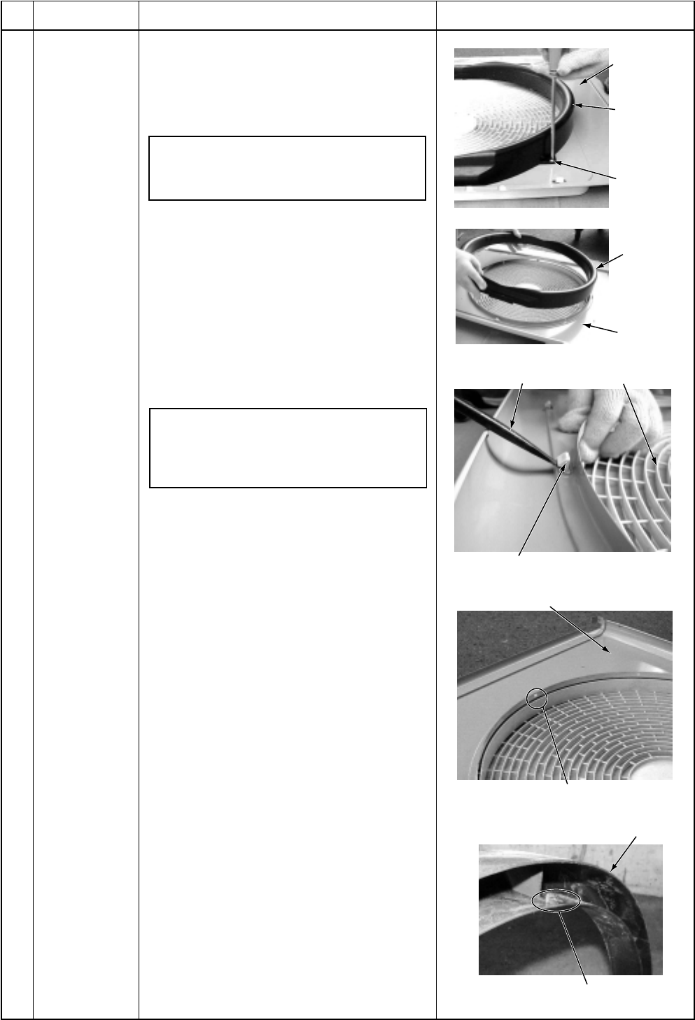
1. Detachment
1) Perform works of items 1 of and .
2) Remove the air flow cabinet, and put it
down so that the fan guard side directs
downward.
Perform work on a corrugated card-
board, cloth, etc. to prevent flaw to the
product.
3) Take off screws fixing the bell mouth.
(ST1Tf4 x 10L, 2 pcs.)
4) Remove the bell mouth.
5) Remove the hooking claws by pushing
with minus screwdriver along with the
arrow mark as shown in right figure.
2. Attachment
1) Insert claw of the fan guard in hole of the
discharge panel. Push the hooking claws
(5 positions) with hands and fix the claws.
After all the attachment works are
completed, check that all the hooking
claws are fixed to the specified posi-
tions.
2) Mount the bell mouth by hooking three
claws at upper side of the bell mouth in the
slits on the discharge cabinet.
3) After attachment, fix the bell mouth with
screws. (ST1Tf4 x 10L, 2 pcs.)
Remarks
Discharge
port cabinet
Bell mouth
Remove
two screws
Discharge
port cabinet
Bell mouth
Minus screwdriver
Fan guard
Hooking claw
Discharge port cabinet
Slit (3 positions)
Claw (3 positions)
Bell mouth


